Toyota 4Runner: Removal
REMOVAL
PROCEDURE
1. REMOVE INSTRUMENT PANEL SUB-ASSEMBLY
(a) Remove the instrument panel sub-assembly (See page
.gif) ).
).
2. REMOVE NO. 1 HEATER TO REGISTER DUCT
3. REMOVE NO. 2 HEATER TO REGISTER DUCT
4. REMOVE NO. 1 SIDE DEFROSTER NOZZLE DUCT
5. REMOVE NO. 2 SIDE DEFROSTER NOZZLE DUCT
6. REMOVE NO. 3 HEATER TO REGISTER DUCT
7. REMOVE AUTOMATIC LIGHT CONTROL SENSOR
|
(a) Disconnect the connector. |
|
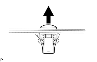
(b) Detach the 2 claws and remove the sensor.
 On-vehicle Inspection
ON-VEHICLE INSPECTION
PROCEDURE
1. CHECK AUTOMATIC LIGHT CONTROL SENSOR
(a) Measure the voltage according to the value(s) in the table below.
Standard Voltage:
Te ...
 Installation
INSTALLATION
PROCEDURE
1. INSTALL AUTOMATIC LIGHT CONTROL SENSOR
(a) Attach the 2 claws to install the sensor.
(b) Connect the connector.
2. I ...
Other materials about Toyota 4Runner:
Installation
INSTALLATION
CAUTION / NOTICE / HINT
HINT:
A bolt without a torque specification is shown in the standard bolt chart (See
page ).
PROCEDURE
1. INSTALL DECK SIDE TRIM CUP HOLDER LH (w/ Rear No. 2 Seat)
(a) Attach the 2 claws to install the deck side tr ...
Precaution
PRECAUTION
1. IGNITION SWITCH EXPRESSION
HINT:
The type of ignition switch used on this model differs according to the specifications
of the vehicle. The expressions listed in the table below are used in this section.
Expression
Ign ...
0.028