Toyota 4Runner: Removal
REMOVAL
PROCEDURE
1. DRAIN ENGINE COOLANT
(a) Drain engine coolant (See page .gif) ).
).
2. RECOVER REFRIGERANT FROM REFRIGERATION SYSTEM
3. DISCONNECT CABLE FROM NEGATIVE BATTERY TERMINAL
CAUTION:
Wait at least 90 seconds after disconnecting the cable from the negative (-) battery terminal to disable the SRS system.
NOTICE:
When disconnecting the cable, some systems need to be initialized after the cable
is reconnected (See page ).
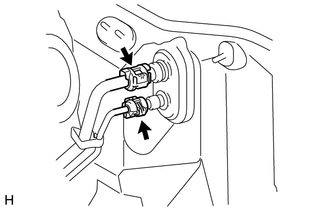
4. DISCONNECT AIR CONDITIONING TUBE AND ACCESSORY ASSEMBLY
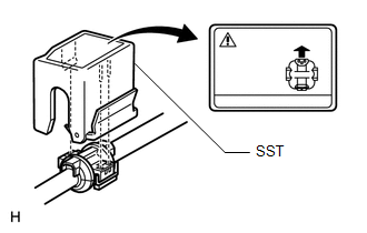
(a) Using SST, remove the piping clamp.
SST: 09870-00015
SST: 09870-00025
|
(1) Attach SST to the piping clamp. HINT: Confirm the direction of the piping clamp claw and SST by referring to the illustration on the caution label. |
|
|
(2) Push down SST and release the clamp lock. Text in Illustration
NOTICE: Be careful not to deform the tubes when pushing SST. |
|
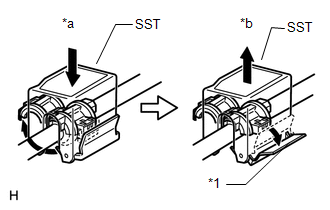
(3) Pull SST slightly and push the release lever, and then remove the piping clamp with SST.
(4) Remove the piping clamp from SST.
(b) Disconnect the air conditioning tube and accessory assembly.
NOTICE:
Cap the open fittings immediately to keep moisture and dirt out of the system.
(c) Remove the grommet.
5. DISCONNECT INLET HEATER WATER HOSE AND OUTLET HEATER WATER HOSE
|
(a) Using pliers, grip the claws of the clips and slide the 2 clips. |
|
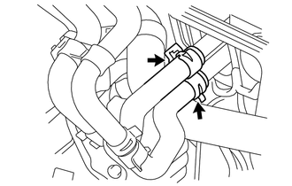
(b) Disconnect the 2 heater water hoses.
6. REMOVE WINDSHIELD WIPER MOTOR ASSEMBLY
(a) Remove the windshield wiper motor assembly (See page
).
7. REMOVE INSTRUMENT PANEL SUB-ASSEMBLY
(a) Remove the instrument panel (See page ).
8. REMOVE STEERING COLUMN ASSEMBLY
(a) Remove the steering column (See page ).
9. REMOVE FRONT SEAT ASSEMBLY LH
(a) for Manual Seat:
Remove the front seat assembly LH (See page
).
(b) for Power Seat:
Remove the front seat assembly LH (See page
).
10. REMOVE FRONT SEAT ASSEMBLY RH
HINT:
Use the same procedure described for the LH side.
(a) for Manual Seat:
Remove the front seat assembly RH (See page
).
(b) for Power Seat:
Remove the front seat assembly RH (See page
).
11. REMOVE FRONT FLOOR CARPET ASSEMBLY
HINT:
It is not necessary to fully remove the floor carpet. Partially remove it so that the rear air duct can be removed in a later step.
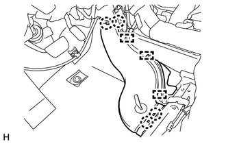
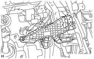
12. REMOVE REAR NO. 3 AIR DUCT
|
(a) Detach the 3 clamps and 4 claws and remove the rear No. 3 air duct. |
|
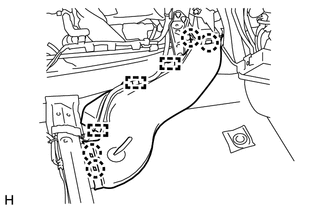
13. REMOVE REAR NO. 1 AIR DUCT
|
(a) Detach the 3 clamps and 4 claws and remove the rear No. 1 air duct. |
|
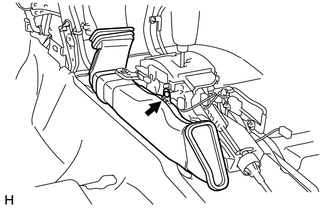
14. REMOVE NO. 1 CONSOLE BOX DUCT
|
(a) Remove the clip and No. 1 console box duct. |
|
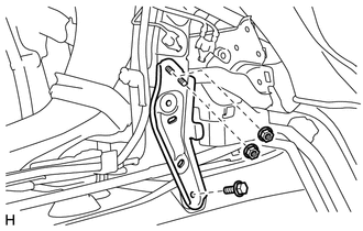
15. REMOVE NO. 1 INSTRUMENT PANEL BRACE MOUNTING BRACKET LH
|
(a) Remove the 2 nuts, bolt and instrument panel brace. |
|
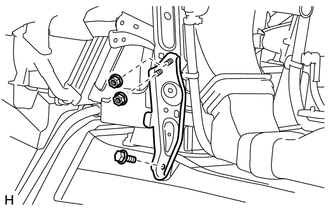
16. REMOVE NO. 1 INSTRUMENT PANEL BRACE MOUNTING BRACKET RH
|
(a) Remove the 2 nuts, bolt and instrument panel brace. |
|
17. REMOVE NO. 1 AIR DUCT SUB-ASSEMBLY
|
(a) Detach the 3 claws and remove the duct. |
|
18. REMOVE NO. 2 AIR DUCT SUB-ASSEMBLY
|
(a) Remove the screw. |
|
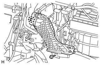
(b) Detach the 2 claws and remove the air duct.
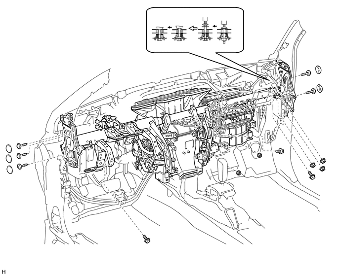
19. REMOVE INSTRUMENT PANEL REINFORCEMENT ASSEMBLY WITH AIR CONDITIONING UNIT ASSEMBLY
(a) Detach the clamps and disconnect the connectors and wire harness.
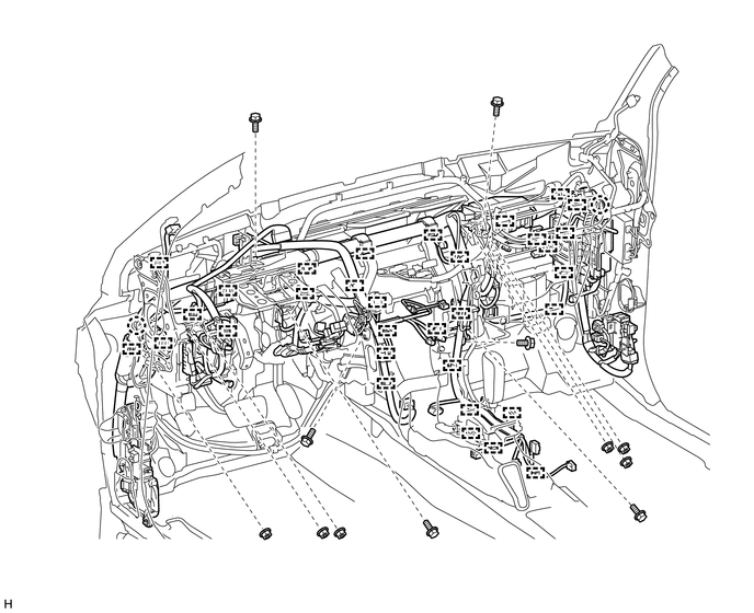
(b) Remove the instrument panel reinforcement assembly with air conditioning unit assembly.
(1) Remove the 5 caps.
(2) Using a T40 "TORX" socket, remove the 5 "TORX" bolts.
(3) Using a 12 mm hexagon wrench, loosen the 2 collars.
(4) Remove the bolts, nuts and instrument panel reinforcement assembly with air conditioning unit assembly.
20. REMOVE INSTRUMENT PANEL REINFORCEMENT ASSEMBLY
|
(a) Remove the 5 bolts. |
|
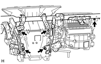
(b) Detach the 2 claws and remove the instrument panel reinforcement assembly.
 Disassembly
DISASSEMBLY
PROCEDURE
1. REMOVE BLOWER ASSEMBLY
(a) Remove the bolt.
(b) Detach the 2 claws and remove the blower unit assembly.
2. REMOVE DEF ...
 Installation
INSTALLATION
CAUTION / NOTICE / HINT
HINT:
A bolt without a torque specification is shown in the standard bolt chart (See
page ).
PROCEDURE
1. INSTALL INSTRUMENT PANEL REINFORCEMENT ASSEMBLY
...
Other materials about Toyota 4Runner:
Cellular Phone Inspection
CAUTION / NOTICE / HINT
HINT:
If the operation of a cellular phone or the navigation receiver assembly is requested,
make sure to follow the instructions closely and perform the operation.
PROCEDURE
1.
CHECK USAGE CONDITION
...
Problem Symptoms Table
PROBLEM SYMPTOMS TABLE
HINT:
Use the table below to help determine the cause of problem symptoms. If multiple
suspected areas are listed, the potential causes of the symptoms are listed in order
of probability in the "Suspected Area" column of ...
0.0064