Toyota 4Runner: Removal
REMOVAL
CAUTION / NOTICE / HINT
CAUTION:
Wear protective gloves. Sharp areas on the parts may injure your hands.
HINT:
- Use the same procedure for the RH and LH sides.
- The procedure listed below is for the LH side.
PROCEDURE
1. REMOVE DECK BOARD ASSEMBLY
(a) Pull the 2 rear seat lock release straps and fold down the 2 headrests.
(b) Operate the 2 rear seat lock release levers and fold down the 2 seatbacks.
|
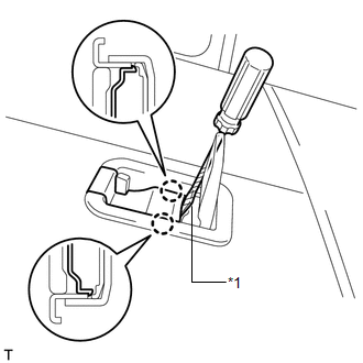
(c) Using a screwdriver, detach the 2 claws and open the cover. Text in Illustration
HINT:
|
|
|
(d) Remove the 2 bolts. |
|
(e) Detach the 4 clips and remove the deck board.
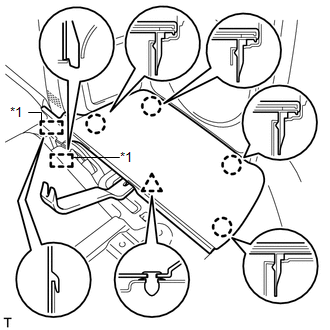
2. REMOVE REAR FLOOR MAT SUPPORT PLATE
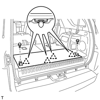
(a) Remove the 3 bolts.
 Text in Illustration
|
*1 |
Guide |
- |
- |
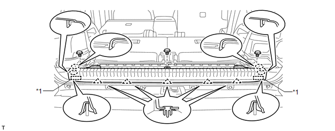
(b) Detach the 4 claws and 2 guides.
(c) Detach the 5 clips and remove the support plate.
3. REMOVE REAR NO. 4 FLOOR BOARD
|
(a) Using a moulding remover, detach the clip and 4 claws. Text in Illustration
|
|
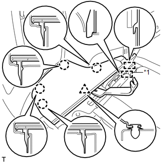
(b) Detach the 2 guides and remove the floor board.
4. REMOVE REAR NO. 3 FLOOR BOARD
|
(a) Using a moulding remover, detach the clip and 4 claws. Text in Illustration
|
|
(b) Detach the 2 guides and remove the floor board.
5. REMOVE DECK BOARD BRACKET REINFORCEMENT
|
(a) Remove the 2 bolts. Text in Illustration
|
|
(b) Detach the 2 hooks and remove the reinforcement.
6. REMOVE NO. 1 DECK BOARD BRACKET LH
|
(a) Remove the 2 bolts and bracket. |
|
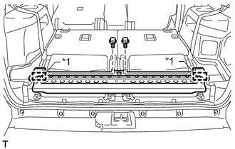
7. REMOVE REAR NO. 2 SEAT ASSEMBLY LH
(a) Operate the seat cushion lock release lever and raise the seatback.
(b) Pull out the seat cushion.
|
(c) Remove the 2 bolts. |
|
|
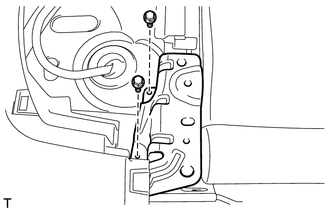
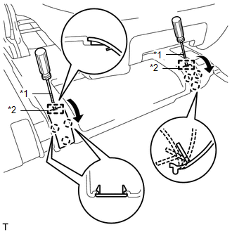
(d) Using a screwdriver, detach the 2 guides and 6 claws and open the 2 covers. Text in Illustration
HINT: Tape the screwdriver tip before use. |
|
|
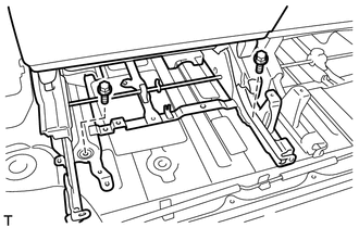
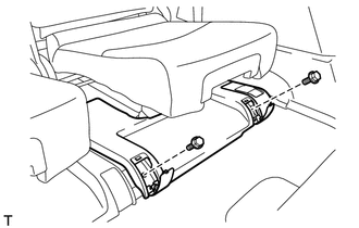
(e) Remove the 2 bolts. |
|
|
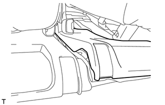
(f) Remove the rear No. 2 seat assembly from the vehicle. NOTICE: Be careful not to damage the vehicle body. HINT: If removing the seat on the RH side with the LH side installed, remove it with the No. 3 rear seat leg cover LH raised as shown in the illustration. |
|
 Reassembly
REASSEMBLY
CAUTION / NOTICE / HINT
CAUTION:
Wear protective gloves. Sharp areas on the parts may injure your hands.
HINT:
Use the same procedure for the RH and LH sides.
The procedure ...
 Installation
INSTALLATION
CAUTION / NOTICE / HINT
CAUTION:
Wear protective gloves. Sharp areas on the parts may injure your hands.
HINT:
Use the same procedure for the RH and LH sides.
The procedu ...
Other materials about Toyota 4Runner:
Disposal
DISPOSAL
CAUTION / NOTICE / HINT
CAUTION:
Before performing pre-disposal deployment of any SRS part, review and closely
follow all applicable environmental and hazardous material regulations. Pre-disposal
deployment may be considered hazardous material ...
Inspection
INSPECTION
PROCEDURE
1. INSPECT FRONT DOOR LOCK ASSEMBLY LH
(a) Check the door lock motor operation.
(1) Apply battery voltage to the motor connector and check the operation of the
door lock.
Text in Illustration
*a
Lock
...
0.0267