Toyota 4Runner: Removal
REMOVAL
PROCEDURE
1. DISCONNECT CABLE FROM NEGATIVE BATTERY TERMINAL
(See page .gif) )
)
2. REMOVE NO. 1 INSTRUMENT CLUSTER FINISH PANEL GARNISH
3. REMOVE NO. 2 INSTRUMENT CLUSTER FINISH PANEL GARNISH
4. REMOVE HEATER CONTROL ASSEMBLY
5. REMOVE RADIO AND DISPLAY RECEIVER ASSEMBLY WITH BRACKET (for Radio and Display Type)
6. REMOVE NAVIGATION RECEIVER ASSEMBLY WITH BRACKETS (for Navigation Receiver Type)
7. REMOVE HAZARD SWITCH WIRE
8. REMOVE NO. 1 RADIO BRACKET
9. REMOVE NO. 2 RADIO BRACKET
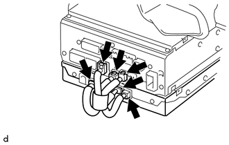
10. REMOVE STEREO COMPONENT TUNER ASSEMBLY
|
(a) Disconnect the 6 connectors to remove the navigation wire and stereo component tuner assembly as shown in the illustration. |
|
 Components
COMPONENTS
ILLUSTRATION
ILLUSTRATION
...
 Installation
INSTALLATION
PROCEDURE
1. INSTALL STEREO COMPONENT TUNER ASSEMBLY
(a) Connect the 6 connectors to the radio and display receiver assembly or navigation
receiver assembly and stereo component tune ...
Other materials about Toyota 4Runner:
Lost Communication with Door Side Airbag Sensor RH (B1692/81,B1697/82)
DESCRIPTION
The circuit for the side collision sensor LH or RH (to determine deployment of
the front seat side airbag LH or RH and curtain shield airbag LH or RH) is composed
of the center airbag sensor, rear airbag sensor LH or RH and side airbag sensor ...
Disassembly
DISASSEMBLY
PROCEDURE
1. REMOVE REAR PROPELLER SHAFT UNIVERSAL JOINT SPIDER BEARING
HINT:
Use the same procedure for all rear propeller shaft universal joint spider bearing.
(a) Place matchmarks on the flange yoke and propeller shaft.
Text i ...
0.0069