Toyota 4Runner: Removal
REMOVAL
PROCEDURE
1. REMOVE PROPELLER SHAFT ASSEMBLY
|
(a) Place matchmarks on the propeller shaft flange and transfer flange. Text in Illustration
|
|
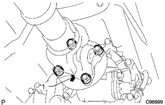
(b) Remove the 4 nuts, 4 washers and propeller shaft assembly.
|
(c) Place matchmarks on the propeller shaft flange and differential flange. Text in Illustration
|
|
.png)
(d) Remove the 4 nuts, 4 bolts and 4 washers.
 Components
COMPONENTS
ILLUSTRATION
...
 Disassembly
DISASSEMBLY
PROCEDURE
1. REMOVE REAR PROPELLER SHAFT UNIVERSAL JOINT SPIDER BEARING
HINT:
Use the same procedure for all rear propeller shaft universal joint spider bearing.
(a) Place ...
Other materials about Toyota 4Runner:
Rear Power Window LH Auto Up / Down Function does not Operate with Rear Power
Window Switch LH
DESCRIPTION
If the auto up/down function does not operate, the cause may be one or more of
the following:
The ECU in the power window regulator motor determines that the power
window regulator motor has not been initialized.
The rear power w ...
Sound Signal Circuit between Navigation Receiver Assembly and Stereo Component
Amplifier
DESCRIPTION
The navigation receiver assembly sends a sound signal to the stereo component
amplifier assembly via the sound signal circuit.
The sound signal that has been sent is amplified by the stereo component amplifier
assembly, and then is sent to th ...
0.0254