Toyota 4Runner: Seat Memory Switch
Components
COMPONENTS
ILLUSTRATION

Removal
REMOVAL
PROCEDURE
1. REMOVE FRONT DOOR LOWER FRAME BRACKET GARNISH LH
.gif)
2. REMOVE NO. 2 DOOR INSIDE HANDLE BEZEL LH
3. REMOVE FRONT DOOR TRIM BOARD SUB-ASSEMBLY LH
4. REMOVE FRONT DOOR INNER GLASS WEATHERSTRIP LH
5. REMOVE SEAT MEMORY SWITCH
|
(a) Disconnect the connector. |
|
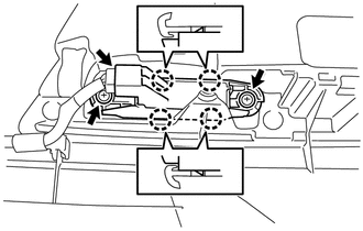
(b) Remove the 2 screws.
(c) Detach the 4 claws to remove the seat memory switch.
Inspection
INSPECTION
PROCEDURE
1. INSPECT SEAT MEMORY SWITCH
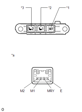
(a) Measure the resistance according to the value(s) in the table below.
Standard Resistance:
|
Tester Connection |
Switch Condition |
Specified Condition |
|---|---|---|
|
3 (M1) - 1 (E) |
1 switch pressed |
Below 1 Ω |
|
4 (M2) - 1 (E) |
2 switch pressed |
|
|
2 (MRY) - 1 (E) |
SET switch pressed |
If the result is not as specified, replace the seat memory switch.
Text in Illustration|
*1 |
SET Switch |
|
*2 |
1 Switch |
|
*3 |
2 Switch |
|
*a |
Component without harness connected (Seat Memory Switch) |
Installation
INSTALLATION
PROCEDURE
1. INSTALL SEAT MEMORY SWITCH
(a) Attach the 4 claws to install the seat memory switch.
(b) Install the 2 screws.
(c) Connect the connector.
2. INSTALL FRONT DOOR INNER GLASS WEATHERSTRIP LH
.gif)
3. INSTALL FRONT DOOR TRIM BOARD SUB-ASSEMBLY LH
4. INSTALL NO. 2 DOOR INSIDE HANDLE BEZEL LH
5. INSTALL FRONT DOOR LOWER FRAME BRACKET GARNISH LH
 On-vehicle Inspection
ON-VEHICLE INSPECTION
PROCEDURE
1. INSPECT SEAT HEATER CONTROL SUB-ASSEMBLY LH
(a) Disconnect the b2 seat heater control sub-assembly LH connector.
...
 Seat Belt
...
Other materials about Toyota 4Runner:
Tires
Replace or rotate tires in accordance with maintenance schedules and
treadwear.
Checking tires
1. New tread
2. Treadwear indicator
3. Worn tread
The location of treadwear indicators is shown by the “TWI” or “Δ” marks,
etc., molded on the ...
Data List / Active Test
DATA LIST / ACTIVE TEST
1. READ DATA LIST
HINT:
Using the Techstream to read the Data List allows the values or states of switches,
sensors, actuators and other items to be read without removing any parts. This non-intrusive
inspection can be very usefu ...
0.011