Toyota 4Runner: Sliding Roof ECU Power Source Circuit
DESCRIPTION
If the sliding function and tilt function do not operate, there may be a malfunction in the sliding roof drive gear sub-assembly power source circuit.
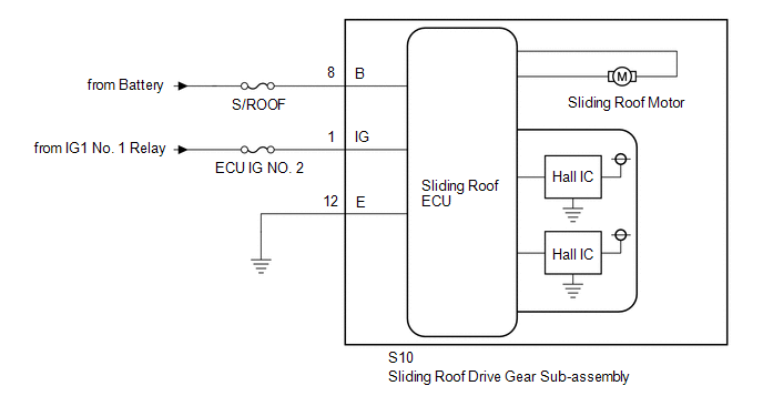
WIRING DIAGRAM
CAUTION / NOTICE / HINT
NOTICE:
- When the sliding roof drive gear sub-assembly (sliding roof ECU) is
removed and reinstalled or replaced, the sliding roof drive gear sub-assembly
(sliding roof ECU) must be initialized (See page
.gif) ).
). - Inspect the fuses for circuits related to this system before performing the following inspection procedure.
PROCEDURE
|
1. |
CHECK HARNESS AND CONNECTOR (SLIDING ROOF DRIVE GEAR SUB-ASSEMBLY (SLIDING ROOF ECU) - BATTERY AND BODY GROUND) |
|
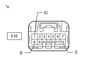
*a |
Front view of wire harness connector (to Sliding Roof Drive Gear Sub-assembly (Sliding Roof ECU)) |
(a) Disconnect the S10 sliding roof drive gear sub-assembly (sliding roof ECU) connector.
(b) Measure the resistance and voltage according to the value(s) in the table below.
Standard Voltage:
|
Tester Connection |
Switch Condition |
Specified Condition |
|---|---|---|
|
S10-8 (B) - Body ground |
Always |
11 to 14 V |
|
S10-1 (IG) - Body ground |
Ignition switch off |
Below 1 V |
|
S10-1 (IG) - Body ground |
Ignition switch ON |
11 to 14 V |
Standard Resistance
|
Tester Connection |
Condition |
Specified Condition |
|---|---|---|
|
S10-12 (E) - Body ground |
Always |
Below 1 Ω |
| OK | .gif) |
REPLACE SLIDING ROOF DRIVE GEAR SUB-ASSEMBLY (SLIDING ROOF ECU) |
| NG | |
REPAIR OR REPLACE HARNESS OR CONNECTOR |
 Sliding Roof Control Switch Circuit
DESCRIPTION
The sliding roof drive gear sub-assembly (sliding roof ECU) receives sliding
roof switch signals and drives its built-in motor.
WIRING DIAGRAM
CAUTION / NOTICE / HINT
NOTICE:
When ...
 Window / Glass
...
Other materials about Toyota 4Runner:
Disassembly
DISASSEMBLY
PROCEDURE
1. REMOVE FRONT NO. 2 AXLE INBOARD JOINT BOOT CLAMP
(a) Hold the drive shaft lightly in a vise between aluminum plates.
(b) Using pliers, remove the front No. 2 axle inboard joint boot clamp
as shown in the illustration ...
Operation Check
OPERATION CHECK
1. CHECK KEY REMINDER WARNING SYSTEM
(a) Check that the key reminder warning buzzer sounds.
(1) With the driver side door closed, insert the key into the ignition key cylinder
and leave the ignition switch off, or turn the ignition switch ...
0.0084