Toyota 4Runner: System Description
SYSTEM DESCRIPTION
1. DESCRIPTION
(a) Safety Connect performs ACN (Automatic Collision Notification), manual emergency calling, stolen vehicle tracking and roadside assistance service, by audio and data communications between the vehicle and call center through the cellular phone network. As shown in the illustration, when a collision is detected, the system sends its location calculated based on GPS signals and the identification code of the DCM (Telematics Transceiver) to a call center. After the necessary information has been gathered, the call center will relay this information to emergency services.
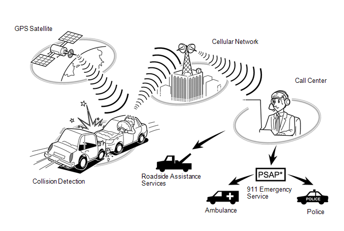
- *: Public Safety Answering Point
2. SYSTEM FUNCTION
|
Function |
Outline |
|---|---|
|
ACN (Automatic Collision Notification) |
When a collision is detected, the vehicle connects to the call center automatically and reports the vehicle location and vehicle information by data communication. The operator will connect to the vehicle and communicate with the occupant. Even if the occupant does not answer, the operator can notify emergency services of the collision. 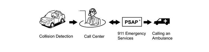 |
|
Manual Emergency Call |
After pressing the manual (SOS) switch, the occupant can talk to an operator from the call center to seek assistance. 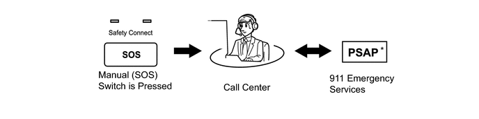 |
|
Stolen Vehicle Locator |
After the vehicle has been reported stolen to the police, the customer can contact the call center to begin the stolen vehicle locator process. The operator locates the vehicle by GPS and provides information to the police. 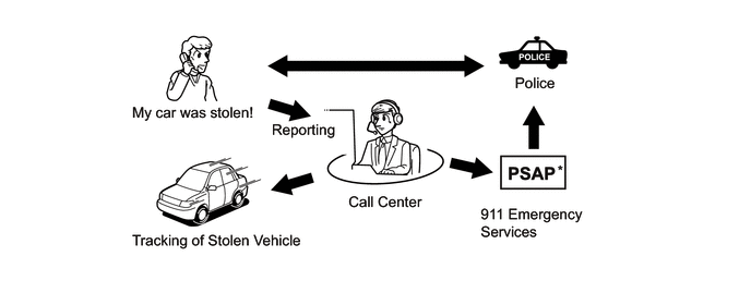 |
|
Roadside Assistance Service |
Pressing the manual (SOS) switch will contact the call center, and a wide range of help, such as towing, flat tire, fuel delivery, etc, Can be provided. 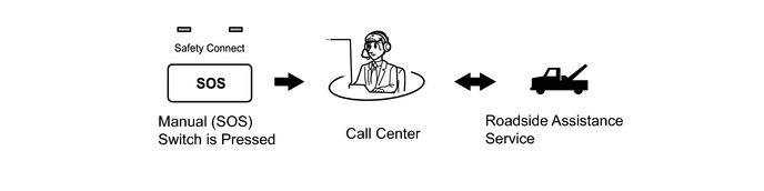 |
- *: Public Safety Answering Point
3. VOICE GUIDANCE FUNCTION
HINT:
This system plays back a voice prompt in certain situations.
|
Voice Prompt |
Usage Condition |
|---|---|
|
Safety Connect failure detected, please contact your dealer. |
When system detects LED failure (Red only). Message is played once at each ignition switch ON until the problem is fixed. |
|
Connecting to the Call Center. |
DCM (Telematics Transceiver) Activation starts. |
|
Safety Connect Activation failed. |
DCM (Telematics Transceiver) Activation fails for some reason. |
|
Safety Connect Activation complete. |
DCM (Telematics Transceiver) Activation completed successfully. |
|
Please make sure you are in an area with good cellular coverage and try again. If you continue to receive this message, contact your dealer. |
Follows activation sequence. |
|
Unable to connect to the Call Center. |
Possible cellular connection or network issue. |
|
Impact detected. |
When DCM (Telematics Transceiver) receives airbag collision signal. |
|
Connecting to the Emergency Call Center. |
Call initiated to call center. |
|
Unable to connect to the Emergency Call Center. |
DCM (Telematics Transceiver) cannot connect to emergency call center for some reason. |
|
To cancel, please press the button again. |
To end call manually. |
|
Emergency call canceled. |
Confirmation that the call has been canceled. |
|
The system will try again. |
Could not connect to call center, the system will redial. |
|
Welcome to Safety Connect. |
This voice prompt is short version for activation. |
|
To activate, please press the button again within 5 seconds. |
This voice prompt is instruction for activation. |
|
Safety Connect is not initialized. |
Reserve for activation. |
|
Safety Connect is not active. |
When DCM (Telematics Transceiver) is in deactive mode. |
|
For information on setting up a new subscription or to initialize a subscription you've already set up, please press the button again within 5 seconds. |
When DCM (Telematics Transceiver) is in deactive mode. |
4. BUB (BACK-UP BATTERY) OUTLINE
(a) The BUB (Back-Up Battery) is a non-rechargeable battery.
(b) When ACN (Automatic Collision Notification) is performed, the BUB (Back-Up Battery) provides power to the DCM (Telematics Transceiver).
NOTICE:
- After ACN is performed, the BUB (Back-Up Battery) must be replaced.
- The BUB (Back-Up Battery) must not be replaced while an ACN call is in progress.
HINT:
When a Manual Emergency Call is made, the BUB (Back-Up Battery) is not used as the power source.
(c) When the BUB (Back-Up Battery) needs to be replaced, the manual (SOS) switch red indicator will come on. The DCM (Telematics Transceiver) will also store a DTC.
5. INDICATOR CONTROL FUNCTION DURING DCM (TELEMATICS TRANSCEIVER) SELF CHECK MODE
HINT:
Every time after the ignition switch is turned to ON, the DCM (Telematics Transceiver) enters a self check mode. The manual (SOS) switch red indicator will illuminate for 2 seconds, and then turn off. Then the manual (SOS) switch green indicator will illuminate and stay on throughout normal operation. The following chart indicates the possible scenarios.
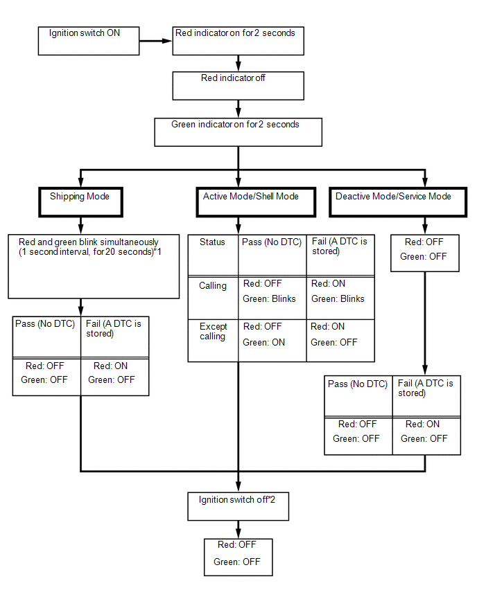
- *1: System will automatically switch to active mode if auto activation is successful.
- *2: If a call is in progress while the ignition switch is off, the call will continue and the LED function will not change.
6. SWITCHING THE CONTRACT MODES
|
Contract Mode |
Description |
|---|---|
|
Shipping Mode |
The mode the DCM (Telematics Transceiver) is in from the factory and during shipping. In this mode, when the ignition switch is turned to ON, the system will automatically attempt to activate active mode. |
|
Shell Mode |
This mode begins when the vehicle is started after arriving at a port or leaving the manufacturing plant line. ACN and stolen vehicle locator are available. |
|
Active Mode |
This mode begins when the owner information is provided to the telematics provider after the customer has entered into a contract with Safety Connect. All functions of Safety Connect are available. |
|
Service Mode |
This mode applies to a new DCM (Telematics Transceiver) that has not been activated after the DCM (Telematics Transceiver) has been replaced. There are no registered phone numbers in the DCM (Telematics Transceiver). |
|
Deactive Mode |
The mode occurs when the Safety Connect subscription has been canceled. |
 System Diagram
SYSTEM DIAGRAM
...
 How To Proceed With Troubleshooting
CAUTION / NOTICE / HINT
HINT:
Use the following procedures to troubleshoot the Safety Connect system.
*: Use the Techstream.
PROCEDURE
1.
VEHICLE BROUGH ...
Other materials about Toyota 4Runner:
Initialization
INITIALIZATION
1. RESET MEMORY
NOTICE:
Perform Reset Memory (AT initialization) when replacing the automatic
transmission assembly, valve body assembly or any of the shift solenoid
valves.
Reset Memory can only be performed with the Tech ...
Satellite Radio Broadcast cannot be Selected or After Selecting Broadcast, Broadcast
cannot be Added into Memory
CAUTION / NOTICE / HINT
NOTICE:
Some satellite radio broadcasts require payment. A contract must be
made between a satellite radio company and the user. If the contract expires,
it will not be possible to listen to the broadcast.
PROCE ...
0.0266