Toyota 4Runner: System Diagram
SYSTEM DIAGRAM
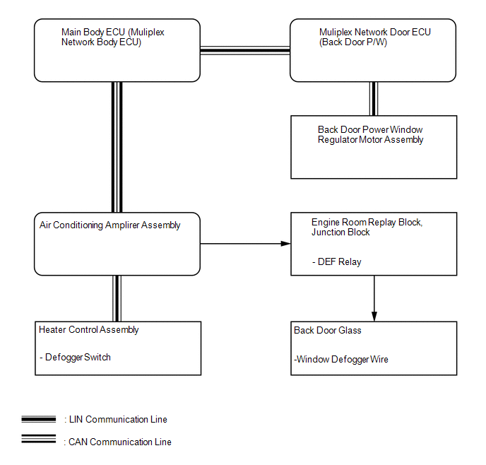 Communication Table
|
Transmitter |
Receiver |
Signal |
Line |
|---|---|---|---|
|
Heater control assembly |
Air conditioning amplifier assembly |
Defogger switch signal |
LIN |
|
Multiplex network door ECU (Back door P/W) |
Main body ECU (Multiplex network body ECU) |
Back door window position signal |
LIN |
|
Back door power window regulator motor |
Multiplex network door ECU (Back door P/W) |
Back door window position signal |
LIN |
|
Main body ECU (Multiplex network body ECU) |
Air conditioning amplifier assembly |
Back door window position signal |
CAN |
 System Description
SYSTEM DESCRIPTION
1. WINDOW DEFOGGER SYSTEM DESCRIPTION
The thin heater wires of the defogger system are attached to the rear window
and defog the rear window surface quickly. The system only ope ...
 How To Proceed With Troubleshooting
CAUTION / NOTICE / HINT
HINT:
Inspect the window defogger system after confirming that the back door
power window system of the power window control system is operating normally.
...
Other materials about Toyota 4Runner:
Parking Brake Switch
Components
COMPONENTS
ILLUSTRATION
Removal
REMOVAL
PROCEDURE
1. DISCONNECT CABLE FROM NEGATIVE BATTERY TERMINAL
CAUTION:
Wait at least 90 seconds after disconnecting the cable from the negative (-)
battery terminal to disable the SRS system.
N ...
Television Camera(for Rear)
Components
COMPONENTS
ILLUSTRATION
Removal
REMOVAL
PROCEDURE
1. REMOVE ASSIST STRAP HOLE COVER
2. REMOVE ASSIST STRAP ASSEMBLY
3. REMOVE BACK DOOR TRIM PANEL ASSEMBLY
4. REMOVE MULTIPLEX NETWORK DOOR ECU
5. REMOVE NO. 2 BACK DOOR SE ...
0.0073