Toyota 4Runner: System Diagram
SYSTEM DIAGRAM
 Communication Table
|
Sender |
Receiver |
Signal |
Line |
|---|---|---|---|
|
ECM |
Skid control ECU |
|
CAN communication |
|
Skid control ECU |
ECM |
|
CAN communication |
|
Skid control ECU |
Combination Meter Assembly |
|
CAN communication |
|
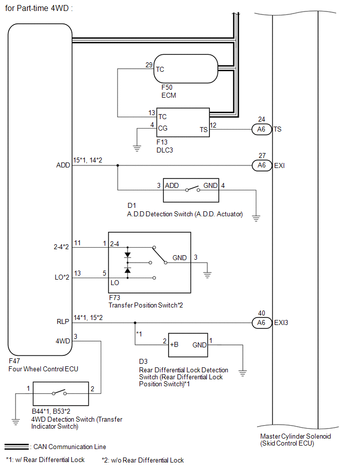
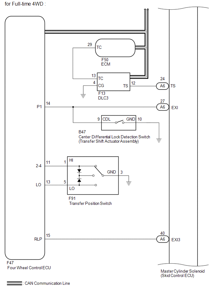
Four wheel drive control ECU |
Skid control ECU |
|
CAN communication |
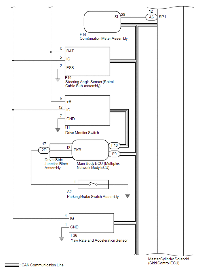
|
Steering Angle Sensor (Spiral Cable Sub-assembly) |
Skid control ECU |
Steering angle signal |
CAN communication |
 Parts Location
PARTS LOCATION
ILLUSTRATION
ILLUSTRATION
...
 System Description
SYSTEM DESCRIPTION
1. SYSTEM DESCRIPTION
HINT:
The skid control ECU is built into the hydraulic brake booster.
(a) ABS (Anti-lock Brake System)
The ABS helps prevent the wheels from locking when ...
Other materials about Toyota 4Runner:
Short to B+ in CAN Bus Line
DESCRIPTION
There may be a short circuit between the CAN bus lines and +B when the resistance
between terminals 6 (CANH) and 16 (BAT) or terminals 14 (CANL) and 16 (BAT) of the
DLC3 is below 6 kΩ.
Symptom
Trouble Area
...
Installation
INSTALLATION
PROCEDURE
1. INSTALL OCCUPANT CLASSIFICATION ECU
(a) Attach the claw to install the occupant classification ECU.
NOTICE:
If the occupant classification ECU has been dropped, or there are any
cracks, dents or other defects i ...
0.0246