Toyota 4Runner: Taillight Relay Circuit
DESCRIPTION
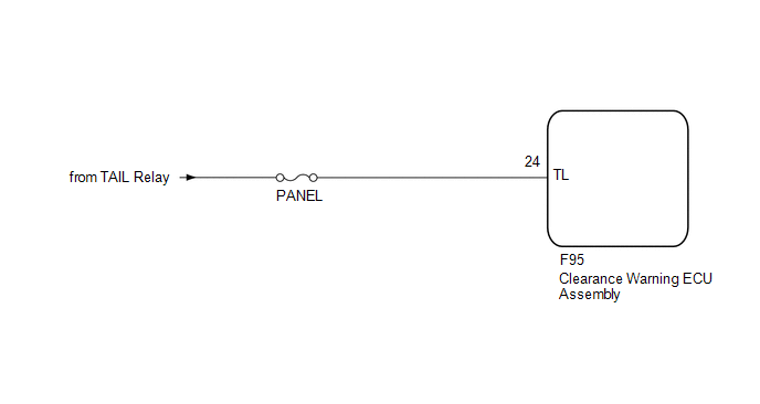
This is the power source circuit of the clearance warning ECU assembly.
WIRING DIAGRAM
CAUTION / NOTICE / HINT
NOTICE:
Inspect the fuses for circuits related to this system before performing the following inspection procedure.
PROCEDURE
|
1. |
CHECK TAILLIGHT |
(a) Turn the light control switch to the TAIL position.
(b) Check that the taillight turns on.
OK:
Taillight turns on.
| NG | .gif) |
GO TO LIGHTING SYSTEM |
|
.gif)
|
2. |
CHECK HARNESS AND CONNECTOR (CLEARANCE WARNING ECU ASSEMBLY - BATTERY) |
|
(a) Disconnect the F95 clearance warning ECU assembly connector. |
|
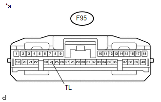
(b) Measure the voltage according to the value(s) in the table below.
Standard Voltage:
|
Tester Connection |
Switch Condition |
Specified Condition |
|---|---|---|
|
F95-24 (TL) - Body ground |
Ignition switch ON, light control switch TAIL |
11 to 14 V |
|
Ignition switch ON, light control switch not TAIL |
Below 1 V |
|
*a |
Front view of wire harness connector (to Clearance Warning ECU Assembly) |
| OK | |
PROCEED TO NEXT SUSPECTED AREA SHOWN IN PROBLEM SYMPTOMS TABLE |
| NG | |
REPAIR OR REPLACE HARNESS OR CONNECTOR |
 Park / Neutral Position Switch Circuit
DESCRIPTION
This circuit sends the park/neutral position switch assembly signals to the clearance
warning ECU assembly.
WIRING DIAGRAM
CAUTION / NOTICE / HINT
NOTICE:
Inspect the fuses for ci ...
 Back Sonar Sensor LH Circuit
DESCRIPTION
The ultrasonic sensor sends and receives ultrasonic waves. Based on the received
wave, the sensor calculates the approximate distance between the vehicle and the
obstacle, and sends t ...
Other materials about Toyota 4Runner:
On-vehicle Inspection
ON-VEHICLE INSPECTION
PROCEDURE
1. INSPECT BRAKE FLUID LEVEL IN RESERVOIR
(a) Check the fluid level and add fluid if necessary.
Brake Fluid:
SAE J1703 or FMVSS No. 116 DOT3
HINT:
Add fluid to the reservoir MAX line.
...
Front Differential Side Gear Shaft Oil Seal(for 4wd)
Components
COMPONENTS
ILLUSTRATION
Replacement
REPLACEMENT
CAUTION / NOTICE / HINT
HINT:
Use the same procedure for the RH and LH sides.
The procedure listed below is for the LH side.
PROCEDURE
1. REMOVE FRONT DRIVE SHAFT ASSEM ...
0.0232