Toyota 4Runner: Terminals Of Ecu
TERMINALS OF ECU
1. CHECK POWER STEERING ECU ASSEMBLY
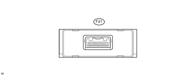
(a) Measure the voltage and resistance according to the value(s) in the table below.
|
Terminal No. (Symbol) |
Wiring Color |
Terminal Description |
Condition |
Specified Condition |
|---|---|---|---|---|
|
F41-3 (GND) - Body ground |
W-B - Body ground |
Ground |
Always |
Below 1 Ω |
|
F41-2 (CANL) - F41-1 (CANH) |
W - L |
CAN communication |
Ignition switch off |
54 to 69 Ω |
|
F41-5 (IG) - F41-3 (GND) |
G - W-B |
IG power supply |
Ignition switch ON |
11 to 14 V |
|
F41-7 (SOF+) - F41-8 (SOF-) |
V - LG |
Power steering solenoid valve signal |
|
Pulse generation |
If the result is not as specified, the ECU may have a malfunction.
 Problem Symptoms Table
PROBLEM SYMPTOMS TABLE
HINT:
Use the table below to help determine the cause of problem symptoms.
If multiple suspected areas are listed, the potential causes of the symptoms
are lis ...
 Diagnosis System
DIAGNOSIS SYSTEM
1. CHECK DLC3
(a) Check the DLC3 (See page ).
2. FUNCTION OF POWER STEERING WARNING LIGHT
(a) When a malfunction is detected in the power steering system, the power steering
wa ...
Other materials about Toyota 4Runner:
Washer Nozzle(for Front Side)
Components
COMPONENTS
ILLUSTRATION
On-vehicle Inspection
ON-VEHICLE INSPECTION
PROCEDURE
1. INSPECT WASHER NOZZLE SUB-ASSEMBLY
(a) With the engine running, check the position that the washer fluid hits the
windshield.
Standard:
Washer fluid h ...
Illumination for Panel Switch does not Come on with Tail Switch ON
PROCEDURE
1.
CHECK VEHICLE SIGNAL (OPERATION CHECK)
(a) Enter the "Vehicle Signal Check Mode" screen. Refer to Check Vehicle Signal
in Operation Check (See page ).
(b) Check that the display changes between ON ...
0.027