Toyota 4Runner: Terminals Of Ecu
TERMINALS OF ECU
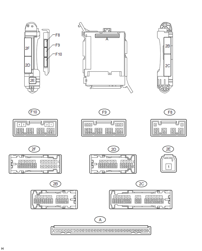
1. CHECK DRIVER SIDE JUNCTION BLOCK ASSEMBLY AND MAIN BODY ECU (MULTIPLEX NETWORK BODY ECU)
(a) Measure the voltage according to the value(s) in the table below.
|
Terminal No. (Symbol) |
Wiring Color |
Terminal Description |
Condition |
Specified Condition |
|---|---|---|---|---|
|
F9-15 (SPD) - 2B-4 (GND1) |
R - W-B |
Speed signal |
Vehicle speed at lower than 8 km/h (5 mph) |
11 to 14 V |
|
Vehicle speed at 8 km/h (5 mph) or more |
Below 1 V |
If the result is not as specified, the main body ECU may have a malfunction.
2. CHECK SIDE AUTO STEP CONTROLLER ECU ASSEMBLY
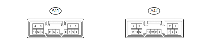
(a) Disconnect the A41 side auto step controller ECU assembly connector.
(b) Measure the voltage and resistance according to the value(s) in the table below.
|
Terminal No. (Symbol) |
Wiring Color |
Terminal Description |
Condition |
Specified Condition |
|---|---|---|---|---|
|
A41-1 (GND) - Body Ground |
W-B - Body Ground |
Ground |
Always |
Below 1 Ω |
|
A41-4 (B) - A41-1 (GND) |
L - W-B |
Battery power supply |
Always |
11 to 14 V |
HINT:
If the result is not as specified, there may be a malfunction on the wire harness side.
(c) Reconnect the A41 side auto step controller ECU assembly connector.
(d) Measure the voltage and resistance according to the value(s) in the table below.
|
Terminal No. (Symbol) |
Wiring Color |
Terminal Description |
Condition |
Specified Condition |
|---|---|---|---|---|
|
A41-5 (SSR-) - A41-1 (GND) |
GR - W-B |
Ground |
Always |
Below 1 Ω |
|
A41-9 (SSR2) - A41-1 (GND) |
L - W-B |
Side auto step motor hall sensor RH signal |
When the automatic running board RH is being deployed or stowed |
Pulse generation (See waveform 1) |
|
A41-10 (SSR1) - A41-1 (GND) |
W - W-B |
Side auto step motor hall sensor LH signal |
When the automatic running board LH is being deployed or stowed |
Pulse generation (See waveform 1) |
|
A41-14 (SSR+) - A41-1 (GND) |
LG - W-B |
Side auto step hall sensor power supply |
When the automatic running board is being deployed or stowed |
8 to 11 V |
|
A42-1 (DPL2) - A41-1 (GND) |
G - W-B |
Side auto step motor RH operation signal |
Passenger side door is opened When the automatic running board RH is being deployed |
11 to 14 V |
|
A42-2 (STW2) - A41-1 (GND) |
R - W-B |
Side auto step motor RH operation signal |
Passenger side door is closed When the automatic running board RH is being stowed |
11 to 14 V |
|
A42-3 (STW1) - A41-1 (GND) |
P - W-B |
Side auto step motor LH operation signal |
Driver side door is closed When the automatic running board LH is being stowed |
11 to 14 V |
|
A42-4 (DPL1) - A41-1 (GND) |
V - W-B |
Side auto step motor LH operation signal |
Driver side door is opened When the automatic running board LH is being deployed |
11 to 14 V |
|
A42-9 (FOUT) - A41-1 (GND) |
GR - W-B |
Ground |
Always |
Below 1 V |
|
A42-10 (FIN) - A41-1 (GND) |
W - W-B |
Ground |
Always |
Below 1 V |
|
A42-11 (SP1+) - A41-1 (GND) |
R - W-B |
Speed signal |
Vehicle speed at lower than 8 km/h (5 mph) |
11 to 14 V |
|
Vehicle speed at 8 km/h (5 mph) or more |
Below 1 V |
|||
|
A42-12 (IND) - A41-1 (GND) |
G - W-B |
Warning light drive output |
Warning light on |
11 to 14 V |
|
Warning light off |
Below 1 V |
|||
|
A42-13 (CTY2) - A41-1 (GND) |
R - W-B |
Door courtesy light switch RH signal |
Rear door RH open |
Below 1 V |
|
Rear door RH closed |
11 to 14 V |
|||
|
A42-14 (CTY1) - A41-1 (GND) |
L - W-B |
Door courtesy light switch LH signal |
Rear door LH open |
Below 1 V |
|
Rear door LH closed |
11 to 14 V |
(e) Using an oscilloscope, check the waveform 1.
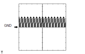 Waveform 1 (Reference)
|
Item |
Content |
|---|---|
|
Tool Setting |
5 V/DIV., 5 ms/DIV. |
|
Condition |
When the automatic running board is being deployed or stowed |
 Problem Symptoms Table
PROBLEM SYMPTOMS TABLE
HINT:
Use the table below to help determine the cause of problem symptoms.
If multiple suspected areas are listed, the potential causes of the symptoms
are lis ...
 Diagnosis System
DIAGNOSIS SYSTEM
1. FUNCTION OF AUTOMATIC RUNNING BOARD WARNING LIGHT
(a) When a malfunction is detected in the automatic running board system, the
automatic running board warning light in the com ...
Other materials about Toyota 4Runner:
If the vehicle battery is discharged
The following procedures may be used to start the engine if the vehicle's
battery is discharged.
You can also call your Toyota dealer or a qualified repair shop.
If you have a set of jumper (or booster) cables and a second vehicle with a
12-volt batt ...
Speed Sensor
Components
COMPONENTS
ILLUSTRATION
Removal
REMOVAL
PROCEDURE
1. REMOVE SPEED SENSOR NT
(a) Disconnect the sensor connector.
(b) Remove the bolt and sensor.
(c) Remove the O-ring from the sensor.
2. REMOVE SPEED SENSOR SP2
(a) Disconnect th ...
0.0085