Toyota 4Runner: Terminals Of Ecu
TERMINALS OF ECU
1. CHECK SLIDING ROOF DRIVE GEAR SUB-ASSEMBLY (SLIDING ROOF ECU)

(a) Disconnect the S10 sliding roof drive gear sub-assembly connector.
(b) Measure the resistance and voltage according to the value(s) in the table below.
HINT:
Measure the values on the wire harness side with the connector disconnected.
|
Terminal No. (Symbol) |
Wiring Color |
Terminal Description |
Condition |
Specified Condition |
|---|---|---|---|---|
|
S10-8 (B) - S10-12 (E) |
W - W-B |
Battery power supply |
Always |
11 to 14 V |
|
S10-1 (IG) - S10-12 (E) |
L - W-B |
IG power supply |
Ignition switch off |
Below 1 V |
|
S10-1 (IG) - S10-12 (E) |
L - W-B |
IG power supply |
Ignition switch ON |
11 to 14 V |
|
S10-12 (E) - Body ground |
W-B - Body ground |
Ground |
Always |
Below 1 Ω |
- If the result is not as specified, there may be a malfunction on the wire harness side.
(c) Reconnect the S10 sliding roof drive gear sub-assembly connector.
(d) Measure the voltage according to the value(s) in the table below.
|
Terminal No. (Symbol) |
Wiring Color |
Terminal Description |
Condition |
Specified Condition |
|---|---|---|---|---|
|
S10-7 (OPN) - S10-12 (E) |
LG - W-B |
Sliding roof motor open |
Ignition switch ON, sliding roof closed Slide open switch off |
11 to 14 V |
|
S10-7 (OPN) - S10-12 (E) |
LG - W-B |
Sliding roof motor open |
Ignition switch ON, sliding roof closed Slide open switch on |
Below 1 V |
|
S10-5 (CLS) - S10-12 (E) |
B - W-B |
Sliding roof motor close |
Ignition switch ON, sliding roof open Slide close switch off |
11 to 14 V |
|
S10-5 (CLS) - S10-12 (E) |
B - W-B |
Sliding roof motor close |
Ignition switch ON, sliding roof open Slide close switch on |
Below 1 V |
|
S10-4 (UP) - S10-12 (E) |
R - W-B |
Sliding roof motor up |
Ignition switch ON, sliding roof tilted downward Tilt up switch off |
11 to 14 V |
|
S10-4 (UP) - S10-12 (E) |
R - W-B |
Sliding roof motor up |
Ignition switch ON, sliding roof tilted downward Tilt up switch on |
Below 1 V |
|
S10-6 (DWN) - S10-12 (E) |
P - W-B |
Sliding roof motor down |
Ignition switch ON, sliding roof tilted upward Tilt down switch off |
11 to 14 V |
|
S10-6 (DWN) - S10-12 (E) |
P - W-B |
Sliding roof motor down |
Ignition switch ON, sliding roof tilted upward Tilt down switch on |
Below 1 V |
- If the result is not as specified, the sliding roof drive gear sub-assembly may have a malfunction.
2. CHECK DRIVER SIDE JUNCTION BLOCK ASSEMBLY, MAIN BODY ECU (MULTIPLEX NETWORK BODY ECU)
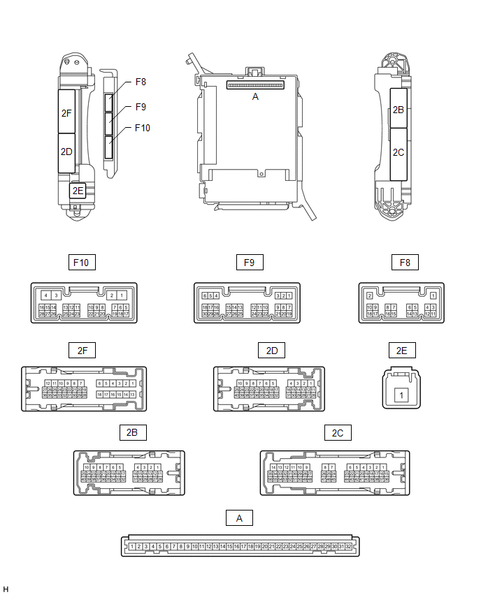
(a) Remove the main body ECU (multiplex network body ECU) from the driver side
junction block assembly (See page .gif) ).
).
(b) Measure the voltage and resistance according to the value(s) in the table below.
HINT:
Measure the values on the wire harness side with the connector disconnected.
|
Terminal No. (Symbol) |
Wiring Color |
Terminal Description |
Condition |
Specified Condition |
|---|---|---|---|---|
|
A-30 (BECU) - Body ground |
- |
Battery power supply |
Ignition switch off |
11 to 14 V |
|
A-31 (ALTB) - Body ground |
- |
Battery power supply |
Ignition switch off |
11 to 14 V |
|
A-32 (IG) - Body ground |
- |
Ignition switch power supply |
Ignition switch ON |
11 to 14 V |
|
A-32 (IG) - Body ground |
- |
Ignition switch power supply |
Ignition switch off |
Below 1 V |
|
A-29 (ACC) - Body ground |
- |
ACC power supply |
Ignition switch ACC |
11 to 14 V |
|
A-29 (ACC) - Body ground |
- |
ACC power supply |
Ignition switch off |
Below 1 V |
|
A-11 (GND1) - Body ground |
- |
Ground |
Always |
Below 1 Ω |
|
F10-3 (GND2) - Body ground |
W-B - Body ground |
Ground |
Always |
Below 1 Ω |
|
F9-17 (KSW)* - Body ground |
B - Body ground |
Unlock warning switch input |
No key in ignition key cylinder |
10 kΩ or higher |
|
F9-17 (KSW)* - Body ground |
B - Body ground |
Unlock warning switch input |
Key in ignition key cylinder |
Below 1 Ω |
- *: w/o Smart Key System
If the result is not as specified, there may be a malfunction in the wire harness.
(c) Reconnect the main body ECU (multiplex network body ECU).
(d) Measure the voltage according to the value(s) in the table below.
|
Terminal No. (Symbol) |
Wiring Color |
Terminal Description |
Condition |
Specified Condition |
|---|---|---|---|---|
|
2F-27 (FLCY) - Body ground |
R - Body ground |
Front door courtesy switch LH input |
Front door LH open |
Below 1 V |
|
2F-27 (FLCY) - Body ground |
R - Body ground |
Front door courtesy switch LH input |
Front door LH closed |
11 to 14 V |
|
2B-15 (FRCY) - Body ground |
B - Body ground |
Front door courtesy switch RH input |
Front door RH open |
Below 1 V |
|
2B-15 (FRCY) - Body ground |
B - Body ground |
Front door courtesy switch RH input |
Front door RH closed |
11 to 14 V |
|
F9-11 (L2) - Body ground |
LG - Body ground |
Driver side door key-linked lock input |
Driver side door key cylinder turned to lock |
Below 1 V |
|
F9-11 (L2) - Body ground |
LG - Body ground |
Driver side door key-linked lock input |
Driver side door key cylinder off |
11 to 14 V |
|
F9-24 (UL3) - Body ground |
GR - Body ground |
Driver side door key-linked unlock input |
Driver side door key cylinder turned to unlock |
Below 1 V |
|
F9-24 (UL3) - Body ground |
GR - Body ground |
Driver side door key-linked unlock input |
Driver side door key cylinder off |
11 to 14 V |
|
F9-26 (RDA)* - Body ground |
P - Body ground |
Door control receiver input |
No key in ignition key cylinder, all doors closed and transmitter switch off → on |
Pulse generation |
- *: w/o Smart Key System
If the result is not as specified, the main body ECU (multiplex network body ECU) or driver side junction block assembly may have a malfunction.
3. CHECK CERTIFICATION ECU (SMART KEY ECU ASSEMBLY) (w/ Smart Key System)
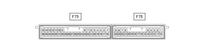
(a) Disconnect the F79 certification ECU (smart key ECU assembly) connector.
(b) Measure the resistance and voltage according to the value(s) in the table below.
HINT:
Measure the values on the wire harness side with the connector disconnected.
|
Terminal No. (Symbol) |
Wiring Color |
Terminal Description |
Condition |
Specified Condition |
|---|---|---|---|---|
|
F79-1 (+B) - F79-15 (E) |
V - W-B |
Battery power supply |
Always |
11 to 14 V |
|
F79-17 (CUTB) - F79-15 (E) |
L - W-B |
Battery power supply |
Always |
11 to 14 V |
|
F79-16 (IG) - F79-15 (E) |
W - W-B |
Ignition power supply |
Ignition switch off → ON |
Below 1 V → 11 to 14 V |
|
F79-15 (E) - Body ground |
W-B - Body ground |
Ground |
Always |
Below 1 Ω |
If the result is not as specified, there may be a malfunction on the wire harness side.
(c) Reconnect the F79 certification ECU (smart key ECU assembly) connector.
(d) Measure the resistance and voltage according to the value(s) in the table below.
|
Terminal No. (Symbol) |
Wiring Color |
Terminal Description |
Condition |
Specified Condition |
|---|---|---|---|---|
|
F78-5 (RCO) - F79-15 (E) |
L - W-B |
Door control receiver power source |
Ignition switch off, all doors closed and transmitter switch not pressed → pressed |
Below 1 V → 4.5 to 5.5 V |
|
F78-15 (RDA) - F79-15 (E) |
G - W-B |
Door control receiver data input signal |
Ignition switch off |
11 to 14 V pulse generation at regular intervals |
|
F78-16 (RSSI) - F79-15 (E) |
P - W-B |
Door control receiver electric wave existence signal |
All doors locked, all doors closed and transmitter switch not pressed → pressed |
11 to 14 V → Below 2 V |
If the result is not as specified, the certification ECU may have a malfunction.
 Problem Symptoms Table
PROBLEM SYMPTOMS TABLE
HINT:
Use the table below to help determine the cause of problem symptoms.
If multiple suspected areas are listed, the potential causes of the symptoms
are lis ...
 Dtc Check / Clear
DTC CHECK / CLEAR
1. CHECK DTC
(a) Connect the Techstream to the DLC3.
(b) Turn the ignition switch to ON.
(c) Turn the Techstream on.
(d) Enter the following menus: Body Electrical / Sliding Roo ...
Other materials about Toyota 4Runner:
Back Door Garnish(for Side)
Components
COMPONENTS
ILLUSTRATION
Installation
INSTALLATION
PROCEDURE
1. INSTALL BACK DOOR OUTSIDE MOULDING LH
(a) Attach the 5 clips to install the back door outside moulding.
2. INSTALL BACK DOOR OUTSIDE MOULDING RH
HINT:
Use the same proced ...
Removal
REMOVAL
CAUTION / NOTICE / HINT
HINT:
Use the same procedure for the RH and LH sides.
The procedure listed below is for the LH side.
PROCEDURE
1. DISCONNECT CABLE FROM NEGATIVE BATTERY TERMINAL
NOTICE:
When disconnecting the cable, som ...
0.0189