Toyota 4Runner: Terminals Of Ecu
TERMINALS OF ECU
1. CHECK AIR CONDITIONING AMPLIFIER ASSEMBLY
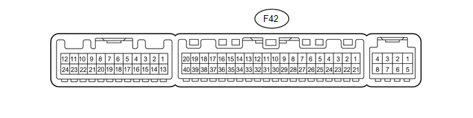
(a) Disconnect the F42 air conditioning amplifier connector.
(b) Measure the voltage and resistance according to the value(s) in the table below.
|
Terminal No. (Symbol) |
Wiring Color |
Terminal Description |
Condition |
Specified Condition |
|---|---|---|---|---|
|
F42-21 (B) - F42-14 (GND) |
V - W-B |
Battery power source |
Always |
11 to 14 V |
|
F42-1 (IG+) - F42-14 (GND) |
L - W-B |
Ignition switch power supply |
Ignition switch ON |
11 to 14 V |
|
F42-1 (IG+) - F42-14 (GND) |
L - W-B |
Ignition switch power supply |
Ignition switch off |
Below 1 V |
|
F42-14 (GND) - Body ground |
W-B - Body ground |
Ground |
Always |
Below 1 Ω |
- If the result is not as specified, there may be a malfunction on the wire harness side.
(c) Reconnect the F42 air conditioning amplifier connector.
(d) Measure the voltage according to the value(s) in the table below.
|
Terminal No. (Symbol) |
Wiring Color |
Terminal Description |
Condition |
Specified Condition |
|---|---|---|---|---|
|
F42-38 (RDEF) - F42-14 (GND) |
P - W-B |
Rear defogger signal |
Ignition switch ON, rear window defogger switch off |
11 to 14 V |
|
F42-38 (RDEF) - F42-14 (GND) |
P - W-B |
Rear defogger signal |
Ignition switch ON, rear window defogger switch on |
Below 1 V |
- If the result is not as specified, there may be a malfunction in the air conditioning amplifier.
2. CHECK HEATER CONTROL ASSEMBLY

(a) Disconnect the F29 heater control connector.
(b) Measure the resistance and voltage according to the value(s) in the table below.
|
Terminal No. (Symbol) |
Wiring Color |
Terminal Description |
Condition |
Specified Condition |
|---|---|---|---|---|
|
F29-4 (IG+) - F29-11 (GND) |
L - W-B |
Ignition switch power supply |
Ignition switch ON |
11 to 14 V |
|
F29-4 (IG+) - F29-11 (GND) |
L - W-B |
Ignition switch power supply |
Ignition switch off |
Below 1 V |
|
F29-11 (GND) - Body ground |
W-B - Body ground |
Ground |
Always |
Below 1 Ω |
If the result is not as specified, there may be a malfunction on the wire harness side.
 Problem Symptoms Table
PROBLEM SYMPTOMS TABLE
HINT:
Use the table below to help determine the cause of problem symptoms.
If multiple suspected areas are listed, the potential causes of the symptoms
are lis ...
 Data List / Active Test
DATA LIST / ACTIVE TEST
1. ACTIVE TEST
HINT:
Using the Techstream to perform Active Tests allows relays, VSVs, actuators and
other items to be operated without removing any parts. This non-intrus ...
Other materials about Toyota 4Runner:
Initialization
INITIALIZATION
1. INITIALIZE SLIDING ROOF DRIVE GEAR SUB-ASSEMBLY
NOTICE:
Before starting this operation, make sure that the guide rails are not
deformed and there is no foreign object on the guide rails.
When the sliding roof glass is adjus ...
Operation Check
OPERATION CHECK
1. CHECK SEAT CUSHION CLIMATE CONTROL BLOWER
(a) Turn the engine switch on (IG).
(b) Set the refreshing seat switch blower side to level 3 (maximum).
(c) Check that the fan motor turns smoothly.
2. CHECK SEATBACK CLIMATE CONTROL BLOWER
(a ...
0.0134