Toyota 4Runner: Terminals Of Ecu
TERMINALS OF ECU
1. CHECK AIR CONDITIONING AMPLIFIER ASSEMBLY
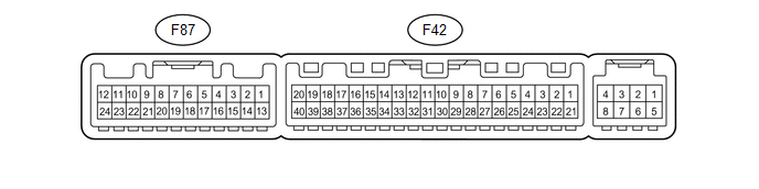
(a) Disconnect the F42 air conditioning amplifier connector.
(b) Measure the voltage and resistance according to the value(s) in the table below.
|
Terminal No. (Symbol) |
Wiring Color |
Terminal Description |
Condition |
Specified Condition |
|---|---|---|---|---|
|
F42-21 (B) - F42-14 (GND) |
V - W-B |
Battery power source |
Always |
11 to 14 V |
|
F42-1 (IG+) - F42-14 (GND) |
L - W-B |
Ignition power supply |
Ignition switch ON |
11 to 14 V |
|
F42-1 (IG+) - F42-14 (GND) |
L - W-B |
Ignition power supply |
Ignition switch off |
Below 1 V |
|
F42-14 (GND) - Body ground |
W-B - Body ground |
Ground |
Always |
Below 1 Ω |
- If the result is not as specified, there may be a malfunction on the wire harness side.
(c) Reconnect the F42 air conditioning amplifier connectors.
(d) Measure the voltage and resistance according to the value(s) in the table below.
|
Terminal No. (Symbol) |
Wiring Color |
Terminal Description |
Condition |
Specified Condition |
|---|---|---|---|---|
|
F42-40 (FDEF) - Body ground |
LG - Body ground |
Windshield deicer relay operation signal |
Ignition switch ON, outer mirror heater switch off |
11 to 14 V |
|
F42-40 (FDEF) - Body ground |
LG - Body ground |
Windshield deicer relay operation signal |
Ignition switch ON, outer mirror heater switch on |
Below 1 V |
|
F87-11 (FDF1) - Body ground |
P - Body ground |
Outer mirror heater switch indicator signal output |
Ignition switch ON, outer mirror heater switch off |
11 to 14 V |
|
F87-11 (FDF1) - Body ground |
P - Body ground |
Outer mirror heater switch indicator signal output |
Ignition switch ON, outer mirror heater switch on |
Below 1 V |
|
F87-5 (SW 1) - Body ground |
R - Body ground |
Outer mirror heater switch signal input |
Ignition switch ON, outer mirror heater switch off |
Below 1 V |
|
F87-5 (SW 1) - Body ground |
R - Body ground |
Outer mirror heater switch signal input |
Ignition switch ON, outer mirror heater switch on |
11 to 14 V |
- If the result is not as specified, the air conditioning amplifier assembly may have a malfunction.
 Problem Symptoms Table
PROBLEM SYMPTOMS TABLE
HINT:
Use the table below to help determine the cause of problem symptoms.
If multiple suspected areas are listed, the potential causes of the symptoms
are lis ...
 Windshield Glass
...
Other materials about Toyota 4Runner:
System Description
SYSTEM DESCRIPTION
1. SYSTEM DESCRIPTION
HINT:
The skid control ECU is built into the hydraulic brake booster.
(a) ABS (Anti-lock Brake System)
The ABS helps prevent the wheels from locking when the brakes are applied firmly
or on a slippery surface.
( ...
Backup Battery Degradation (B15EC)
DESCRIPTION
This DTC is stored when the DCM (Telematics Transceiver) detects either of the
following conditions.
The BUB (Back-Up Battery) charge level becomes less than the criteria.
Automatic Collision Notification (ACN) was performed.
...
0.007