Toyota 4Runner: Terminals Of Ecu
TERMINALS OF ECU
1. CHECK DRIVER SIDE JUNCTION BLOCK ASSEMBLY, MAIN BODY ECU (MULTIPLEX NETWORK BODY ECU)
.png)
(a) Remove the main body ECU (multiplex network body ECU) (See page
.gif) ).
).
(b) Measure the voltage and resistance according to the value(s) in the table below.
|
Terminal No. (Symbol) |
Wiring Color |
Terminal Description |
Condition |
Specified Condition |
|---|---|---|---|---|
|
A-30 (BECU) - Body ground |
- |
Battery power supply |
Always |
11 to 14 V |
|
A-31 (ALTB) - Body ground |
- |
Battery power supply |
Always |
11 to 14 V |
|
A-32 (IG) - Body ground |
- |
Engine switch power supply |
Engine switch on (IG) |
11 to 14 V |
|
A-32 (IG) - Body ground |
- |
Engine switch power supply |
Engine switch off |
Below 1 V |
|
A-29 (ACC) - Body ground |
- |
ACC power supply |
Engine switch on (ACC) |
11 to 14 V |
|
A-29 (ACC) - Body ground |
- |
ACC power supply |
Engine switch off |
Below 1 V |
|
A-11 (GND1) - Body ground |
- |
Ground |
Always |
Below 1 Ω |
|
F10-3 (GND2) - Body ground |
W-B - Body ground |
Ground |
Always |
Below 1 Ω |
If the result is not as specified, there may be a malfunction in the wire harness.
(c) Install the main body ECU (multiplex network body ECU) (See page
).
(d) Measure the voltage according to the value(s) in the table below.
|
Terminal No. (Symbol) |
Wiring Color |
Terminal Description |
Condition |
Specified Condition |
|---|---|---|---|---|
|
2F-27 (FLCY) - Body ground |
R - Body ground |
Front door LH courtesy switch input |
Front door LH open |
Below 1 V |
|
2F-27 (FLCY) - Body ground |
R - Body ground |
Front door LH courtesy switch input |
Front door LH closed |
11 to 14 V |
|
2B-15 (FRCY) - Body ground |
B - Body ground |
Front door RH courtesy switch input |
Front door RH open |
Below 1 V |
|
2B-15 (FRCY) - Body ground |
B - Body ground |
Front door RH courtesy switch input |
Front door RH closed |
11 to 14 V |
|
F8-3 (LCTY) - Body ground |
V - Body ground |
Rear door LH courtesy light switch input |
Rear door LH open |
Below 1 V |
|
F8-3 (LCTY) - Body ground |
V - Body ground |
Rear door LH courtesy light switch input |
Rear door LH closed |
11 to 14 V |
|
F10-27 (RCTY) - Body ground |
R - Body ground |
Rear door RH courtesy light switch input |
Rear door RH open |
Below 1 V |
|
F10-27 (RCTY) - Body ground |
R - Body ground |
Rear door RH courtesy light switch input |
Rear door RH closed |
11 to 14 V |
|
F9-7 (LSFL) - Body ground |
G - Body ground |
Front door LH lock position switch input |
Front door LH unlocked |
Below 1 V |
|
F9-7 (LSFL) - Body ground |
G - Body ground |
Front door LH lock position switch input |
Engine switch off, all doors closed and front door LH locked |
Pulse generation (see waveform 1 or 2) |
|
F9-18 (LSFR) - Body ground |
G - Body ground |
Front door RH lock position switch input |
Front door RH unlocked |
Below 1 V |
|
F9-18 (LSFR) - Body ground |
G - Body ground |
Front door RH lock position switch input |
Engine switch off, all doors closed and front door RH locked |
Pulse generation (see waveform 3 or 4) |
|
2F-25 (LSWL) - Body ground |
V - Body ground |
Rear door LH lock position switch input |
Rear door LH unlocked |
Below 1 V |
|
2F-25 (LSWL) - Body ground |
V - Body ground |
Rear door LH lock position switch input |
Engine switch off, all doors closed and rear door LH locked |
Pulse generation (see waveform 5 or 6) |
|
F10-2 (LSWR) - Body ground |
V - Body ground |
Rear door RH lock position switch input |
Rear door RH unlocked |
Below 1 V |
|
F10-2 (LSWR) - Body ground |
V - Body ground |
Rear door RH lock position switch input |
Engine switch off, all doors closed and rear door RH locked |
Pulse generation (see waveform 7 or 8) |
|
2D-13 (BZR) - Body ground |
GR - Body ground |
Wireless door lock buzzer signal |
Wireless door lock buzzer off |
Below 1 V |
|
2D-13 (BZR) - Body ground |
GR - Body ground |
Wireless door lock buzzer signal |
Wireless door lock buzzer on |
11 to 14 V |
|
F9-3 (HAZ) - Body ground |
W - Body ground |
Hazard warning signal light signal output |
Hazard warning signal switch off |
Below 1 V |
|
F9-3 (HAZ) - Body ground |
W - Body ground |
Hazard warning signal light signal output |
Hazard warning signal switch on |
11 to 14 V |
If the result is not as specified, the main body ECU (multiplex network body ECU) or driver side junction block assembly may have a malfunction.
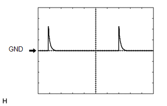
(e) Using an oscilloscope, check waveform 1.
.png) Waveform 1 (Reference)
Waveform 1 (Reference)
|
Item |
Content |
|---|---|
|
Terminal No. (Symbol) |
F9-7 (LSFL) - Body ground |
|
Tool Setting |
5 V/DIV., 20 ms/DIV. |
|
Condition |
Ignition switch off, all doors closed and front door LH locked |
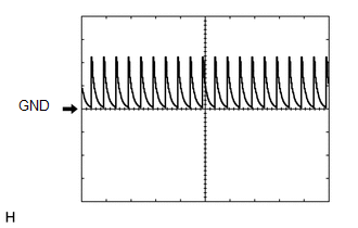
(f) Using an oscilloscope, check waveform 2.
.png) Waveform 2 (Reference)
Waveform 2 (Reference)
|
Item |
Content |
|---|---|
|
Terminal No. (Symbol) |
F9-7 (LSFL) - Body ground |
|
Tool Setting |
5 V/DIV., 20 ms/DIV. |
|
Condition |
Ignition switch off, all doors closed and front door LH locked |
(g) Using an oscilloscope, check waveform 3.
.png) Waveform 3 (Reference)
Waveform 3 (Reference)
|
Item |
Content |
|---|---|
|
Terminal No. (Symbol) |
F9-18 (LSFR) - Body ground |
|
Tool Setting |
5 V/DIV., 20 ms/DIV. |
|
Condition |
Ignition switch off, all doors closed and front door RH locked |
(h) Using an oscilloscope, check waveform 4.
.png) Waveform 4 (Reference)
Waveform 4 (Reference)
|
Item |
Content |
|---|---|
|
Terminal No. (Symbol) |
F9-18 (LSFR) - Body ground |
|
Tool Setting |
5 V/DIV., 20 ms/DIV. |
|
Condition |
Ignition switch off, all doors closed and front door RH locked |
(i) Using an oscilloscope, check waveform 5.
Waveform 5 (Reference)
|
Item |
Content |
|---|---|
|
Terminal No. (Symbol) |
2F-25 (LSWL) - Body ground |
|
Tool Setting |
5 V/DIV., 20 ms/DIV. |
|
Condition |
Ignition switch off, all doors closed and rear door LH locked |
(j) Using an oscilloscope, check waveform 6.
Waveform 6 (Reference)
|
Item |
Content |
|---|---|
|
Terminal No. (Symbol) |
2F-25 (LSWL) - Body ground |
|
Tool Setting |
5 V/DIV., 20 ms/DIV. |
|
Condition |
Ignition switch off, all doors closed and rear door LH locked |
(k) Using an oscilloscope, check waveform 7.
Waveform 7 (Reference)
|
Item |
Content |
|---|---|
|
Terminal No. (Symbol) |
F10-2 (LSWR) - Body ground |
|
Tool Setting |
5 V/DIV., 20 ms/DIV. |
|
Condition |
Ignition switch off, all doors closed and rear door RH locked |
(l) Using an oscilloscope, check waveform 8.
Waveform 8 (Reference)
|
Item |
Content |
|---|---|
|
Terminal No. (Symbol) |
F10-2 (LSWR) - Body ground |
|
Tool Setting |
5 V/DIV., 20 ms/DIV. |
|
Condition |
Ignition switch off, all doors closed and rear door RH locked |
2. CHECK MULTIPLEX NETWORK DOOR ECU (BACK DOOR P/W)
.png)
(a) Disconnect the V2 multiplex network door ECU (back door P/W) connector.
(b) Measure the voltage and resistance according to the value(s) in the table below.
|
Terminal No. (Symbol) |
Wiring Color |
Terminal Description |
Condition |
Specified Condition |
|---|---|---|---|---|
|
V2-1 (BDR) - Body ground |
B - Body ground |
Battery power supply |
Always |
11 to 14 V |
|
V2-7 (BECU) - Body ground |
L - Body ground |
Battery power supply |
Always |
11 to 14 V |
|
V2-8 (SIG) - Body ground |
G - Body ground |
Engine switch power supply |
Engine switch on (IG) |
11 to 14 V |
|
V2-8 (SIG) - Body ground |
G - Body ground |
Engine switch power supply |
Engine switch off |
Below 1 V |
|
V2-6 (GND) - Body ground |
W-B - Body ground |
Ground |
Always |
Below 1 Ω |
If the result is not as specified, there may be a malfunction in the wire harness.
(c) Reconnect the V2 multiplex network door ECU (back door P/W) connector.
(d) Measure the resistance according to the value(s) in the table below.
|
Terminal No. (Symbol) |
Wiring Color |
Terminal Description |
Condition |
Specified Condition |
|---|---|---|---|---|
|
W10-10 (BDCY) - W10-18 (CTYE) |
P - G |
Back door courtesy switch input |
Back door closed |
Pulse generation (see waveform 1 or 2) |
|
W10-10 (BDCY) - W10-18 (CTYE) |
P - G |
Back door courtesy switch input |
Back door open |
Below 1 V |
If the result is not as specified, the multiplex network door ECU (back door P/W) may have a malfunction.
(e) Using an oscilloscope, check waveform 1.
 Waveform 1 (Reference)
|
Item |
Content |
|---|---|
|
Terminal No. (Symbol) |
W10-10 (BDCY) - W10-18 (CTYE) |
|
Tool Setting |
5 V/DIV., 10 ms/DIV. |
|
Condition |
Back door closed |
(f) Using an oscilloscope, check waveform 2.
 Waveform 2 (Reference)
|
Item |
Content |
|---|---|
|
Terminal No. (Symbol) |
W10-10 (BDCY) - W10-18 (CTYE) |
|
Tool Setting |
5 V/DIV., 10 ms/DIV. |
|
Condition |
Back door closed |
3. CHECK CERTIFICATION ECU
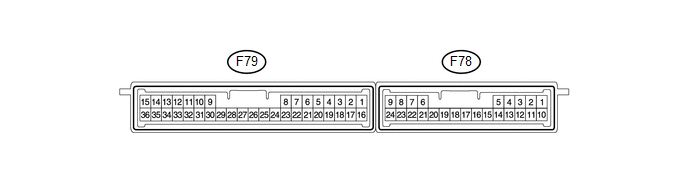
(a) Disconnect the F79 certification ECU connector.
(b) Measure the voltage and resistance according to the value(s) in the table below.
|
Terminal No. (Symbol) |
Wiring Color |
Terminal Description |
Condition |
Specified Condition |
|---|---|---|---|---|
|
F79-1 (+B) - F79-15 (E) |
V - W-B |
+B power supply |
Always |
11 to 14 V |
|
F79-15 (E) - Body ground |
W-B - Body ground |
Ground |
Always |
Below 1 Ω |
|
F79-16 (IG) - F79-15 (E) |
W - W-B |
IG power supply |
Engine switch off → Engine switch on (IG) |
Below 1 V → 11 to 14 V |
|
F79-17 (CUTB) - F79-15 (E) |
L - W-B |
+B power supply |
Always |
11 to 14 V |
- If the result is not as specified, there may be a malfunction in the wire harness.
(c) Reconnect the F79 certification ECU connector.
(d) Measure the voltage according to the value(s) in the table below.
|
Terminal No. (Symbol) |
Wiring Color |
Terminal Description |
Condition |
Specified Condition |
|---|---|---|---|---|
|
F78-5 (RCO) - F79-15 (E) |
L - W-B |
Door control receiver power source |
Engine switch off, all doors closed and transmitter switch not pressed → pressed |
Below 1 V → 4.5 to 5.5 V |
|
F78-15 (RDA) - F79-15 (E) |
G - W-B |
Door control receiver data input signal |
Engine switch off |
11 to 14 V pulse generation at regular intervals |
|
F78-16 (RSSI) - F79-15 (E) |
P - W-B |
Door control receiver electric wave existence signal |
All doors locked, all doors closed and transmitter switch not pressed → pressed |
11 to 14 V → Below 2 V |
- If the result is not as specified, the certification ECU may have a malfunction.
 Problem Symptoms Table
PROBLEM SYMPTOMS TABLE
HINT:
Use the table below to help determine the cause of problem symptoms.
If multiple suspected areas are listed, the potential causes of the symptoms
are lis ...
 Dtc Check / Clear
DTC CHECK / CLEAR
1. CHECK DTC
(a) Connect the Techstream to the DLC3.
(b) Turn the engine switch on (IG).
(c) Turn the Techstream on.
(d) Enter the following menus: Body Electrical / Smart Key / ...
Other materials about Toyota 4Runner:
Engine Coolant Temperature Receiver Gauge Malfunction
DESCRIPTION
In this circuit, the meter CPU receives engine coolant temperature signals from
the ECM using the CAN communication system. The meter CPU displays the engine coolant
temperature, which is calculated based on the data received from the ECM.
WI ...
Motor LH Current Senser (62,63)
DESCRIPTION
When the side auto step motor current detection sensor inside the side auto step
controller ECU assembly detects a current of less than 1 A when the automatic running
board is operating, the side auto step controller ECU assembly does not oper ...
0.0081