Toyota 4Runner: Terminals Of Ecu
TERMINALS OF ECU
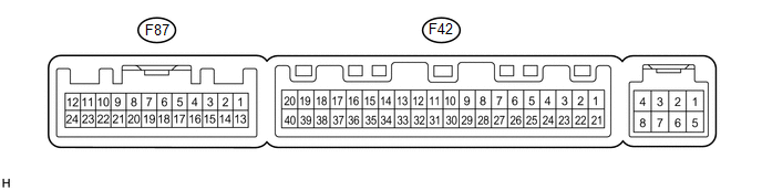
1. AIR CONDITIONING AMPLIFIER
(a) Measure the voltage and resistance according to the value(s) in the table below.
|
Terminal No. (Symbol) |
Wiring Color |
Terminal Description |
Condition |
Specified Condition |
|---|---|---|---|---|
|
F87-9 (ROUT) - Body ground |
LG - Body ground |
Output climate control signal (Front passenger side) |
Engine switch on (IG) Refreshing seat switch RH blower side level 3 |
Pulse generation (see waveform 1) |
|
F87-10 (LOUT) - Body ground |
L - Body ground |
Output climate control signal (Driver side) |
Engine switch on (IG) Refreshing seat switch LH blower side level 3 |
Pulse generation (see waveform 1) |
|
F87-15 (SW 5) - Body ground |
W - Body ground |
Input climate control signal (Front passenger side) |
Engine switch on (IG) Refreshing seat switch RH level 0 |
4.5 to 5.5 V |
|
Engine switch on (IG) Refreshing seat switch RH blower side level 3 |
Below 1 V |
|||
|
F87-16 (SW 4) - Body ground |
V - Body ground |
Input climate control signal (Driver side) |
Engine switch on (IG) Refreshing seat switch LH level 0 |
4.5 to 5.5 V |
|
Engine switch on (IG) Refreshing seat switch LH blower side level 3 |
Below 1 V |
|||
|
F42-31 (S5-4) - Body ground |
V - Body ground |
Power supply |
Engine switch on (IG) |
4.5 to 5.5 V |
|
F42-35 (SG-4) - Body ground |
SB - Body ground |
Ground |
Always |
Below 1 Ω |
If the result is not as specified, the air conditioning amplifier may have a malfunction.
(1) Using an oscilloscope, check waveform 1.
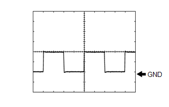 Waveform 1 (Reference)
|
Item |
Content |
|---|---|
|
Terminal No. (Symbol) |
F87-9 (ROUT) - Body ground F87-10 (LOUT) - Body ground |
|
Tool Setting |
2 V/DIV., 500 μsec/DIV. |
|
Condition |
Engine switch on (IG) Refreshing seat switch blower side level 3 |
 On-vehicle Inspection
ON-VEHICLE INSPECTION
PROCEDURE
1. INSPECT SEAT HEATER CONTROL SUB-ASSEMBLY LH
(a) Disconnect the b24 seat heater control sub-assembly LH connector.
...

Other materials about Toyota 4Runner:
Components
COMPONENTS
ILLUSTRATION
ILLUSTRATION
ILLUSTRATION
ILLUSTRATION
ILLUSTRATION
...
Lost Communication with Front Satellite Sensor Bus (B161A/8A)
DESCRIPTION
The front collision sensor circuit (front airbag sensor RH circuit and front
airbag sensor LH circuit) is composed of the center airbag sensor assembly, front
airbag sensor RH and front airbag sensor LH.
The front airbag sensor RH or front ai ...
0.0076