Toyota 4Runner: Terminals Of Ecu
TERMINALS OF ECU
1. CHECK 4WD CONTROL ECU
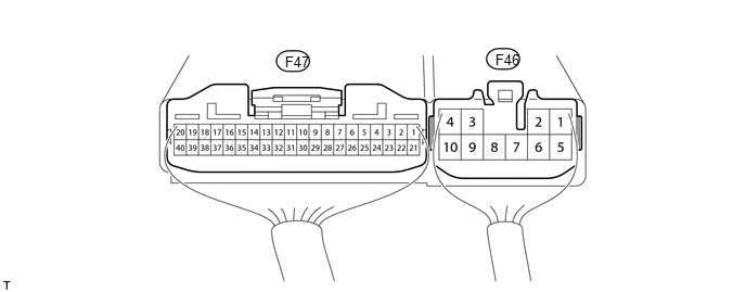
(a) Measure the voltage and resistance according to the value(s) in the table below.
|
Terminal No. (Symbol) |
Wiring Color |
Terminal Description |
Condition |
Specified Condition |
|---|---|---|---|---|
|
F47-6 (RLY1) - F46-4 (GND) |
G - W-B |
Rear differential lock actuator limit switch |
Ignition switch ON Rear differential lock actuator limit switch on |
Below 1.5 V |
|
Ignition switch ON Rear differential lock actuator limit switch off |
11 to 14 V |
|||
|
F47-7 (RLY2) - F46-4 (GND) |
P - W-B |
Rear differential lock actuator limit switch |
Ignition switch ON Rear differential lock actuator limit switch on |
Below 1.5 V |
|
Ignition switch ON Rear differential lock actuator limit switch off |
11 to 14 V |
|||
|
F47-11 (R) - F46-4 (GND) |
SB - W-B |
Rear differential lock switch |
Ignition switch ON Rear differential lock switch on |
Below 1.5 V |
|
Ignition switch ON Rear differential lock switch off |
11 to 14 V |
|||
|
F47-14 (RLP) - F46-4 (GND) |
V - W-B |
Rear differential lock detection switch |
Ignition switch ON Rear differential lock detection switch on |
Below 1.5 V |
|
Ignition switch ON Rear differential lock detection switch off |
9.5 to 14 V |
|||
|
F46-8 (M1) - F46-4 (GND) |
LG - W-B |
Differential lock actuator motor |
Ignition switch ON Differential lock switch off → on (Differential lock switch OFF → ON (For 5 seconds after power supplied or until switching of limit switch is complete during FREE to LOCK switching)) |
11 to 14 V |
|
Ignition switch ON Differential lock switch off → on (Differential lock actuator motor stopped) |
Below 1.5 V |
|||
|
F46-3 (IG) - F46-4 (GND) |
R - W-B |
IG power |
Ignition switch ON |
11 to 14 V |
|
F46-4 (GND) - Body ground |
W-B - Body ground |
Ground |
Always |
Below 1 Ω |
|
F46-7 (M2) - F46-4 (GND) |
L - W-B |
Differential lock actuator motor |
Ignition switch ON Differential lock switch on → off (Differential lock switch ON → OFF (For 5 seconds after power supplied or until switching of limit switch is complete during LOCK to FREE switching)) |
11 to 14 V |
|
Ignition switch ON Differential lock switch on → off (Differential lock actuator motor stopped) |
Below 1.5 V |
|||
|
F47-19 (CANH) - F46-4 (GND) |
G - W-B |
CAN communication line |
Ignition switch ON |
Pulse generation (see waveform 1) |
|
F47-20 (CANL) - F46-4 (GND) |
W - W-B |
CAN communication line |
Ignition switch ON |
Pulse generation (see waveform 2) |
(b) Using an oscilloscope, check waveform 1.
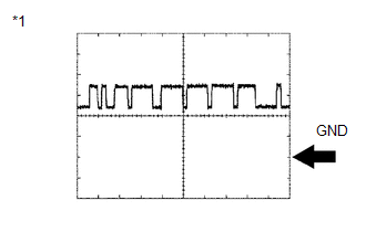 Waveform 1 (Reference)
|
Item |
Content |
|---|---|
|
Terminal No. (Symbols) |
F47-19 (CANH) - F46-4 (GND) |
|
Tool setting |
1 V/DIV., 10 μsec./DIV. |
|
Condition |
Engine stopped and ignition switch ON |
|
*1 |
Waveform 1 |
HINT:
The waveform varies depending on the CAN communication signal.
(c) Using an oscilloscope, check waveform 1.
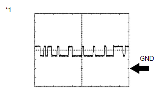 Waveform 2 (Reference)
|
Item |
Content |
|---|---|
|
Terminal No. (Symbols) |
F47-20 (CANL) - F46-4 (GND) |
|
Tool setting |
1 V/DIV., 10 μsec./DIV. |
|
Condition |
Engine stopped and ignition switch ON |
|
*1 |
Waveform 2 |
HINT:
The waveform varies depending on the CAN communication signal.
 Problem Symptoms Table
PROBLEM SYMPTOMS TABLE
HINT:
Use the table below to help determine the cause of problem symptoms.
If multiple suspected areas are listed, the potential causes of the symptoms
are lis ...
 Inspection
INSPECTION
PROCEDURE
1. INSPECT DIFFERENTIAL LOCK SYSTEM
(a) Inspect the indicator light.
(1) Check that the indicator light lights up approximately 1 second after the
ignition switch is turne ...
Other materials about Toyota 4Runner:
Suspension Control System(w/ Reas)
Precaution
PRECAUTION
1. HANDLING PRECAUTIONS FOR CENTER UNIT AND SHOCK ABSORBER
(a) Replacement of each unit is allowed if there is no fluid leakage. However,
in the case of fluid leakage from the system, replace both the absorber and center
unit as ...
Installation
INSTALLATION
CAUTION / NOTICE / HINT
HINT:
Use the same procedure for the RH and LH sides.
The procedure listed below is for the LH side.
A bolt without a torque specification is shown in the standard bolt
chart (See page ).
PROC ...
0.0121