Toyota 4Runner: Unlock Warning Switch
Components
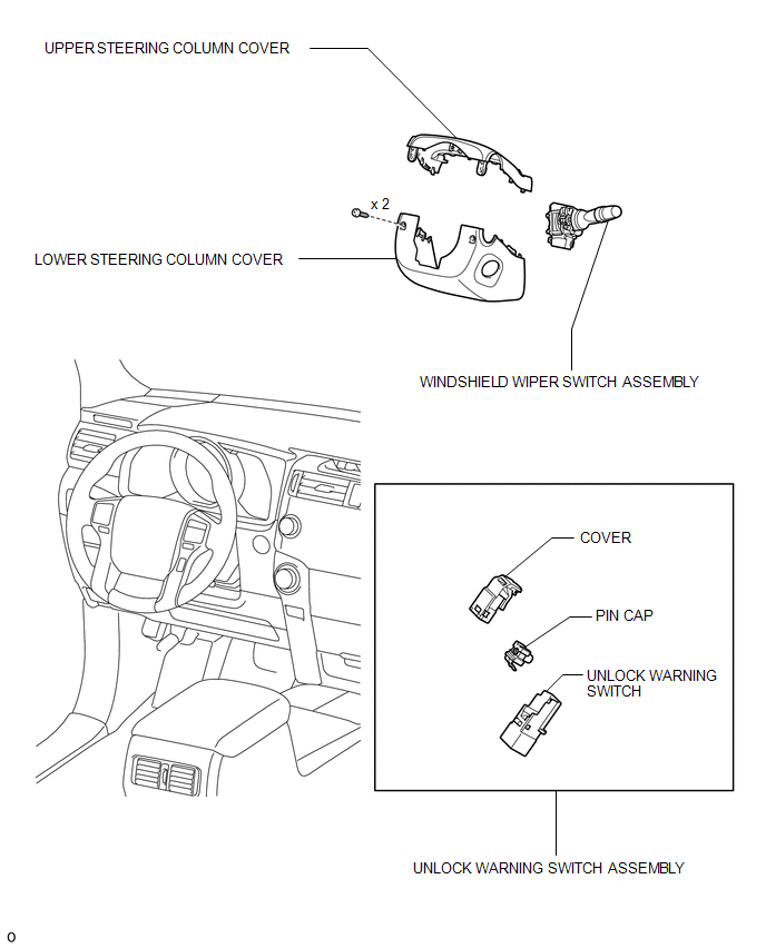
COMPONENTS
ILLUSTRATION
Removal
REMOVAL
PROCEDURE
1. REMOVE LOWER STEERING COLUMN COVER
.gif)
2. REMOVE UPPER STEERING COLUMN COVER
3. REMOVE WINDSHIELD WIPER SWITCH ASSEMBLY
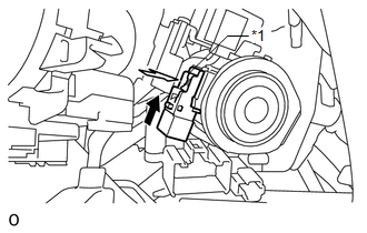
4. REMOVE UNLOCK WARNING SWITCH ASSEMBLY
|
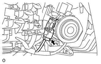
(a) Disconnect the unlock warning switch connector. |
|
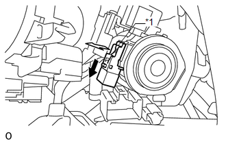
(b) Detach the 3 claws and remove the cover.
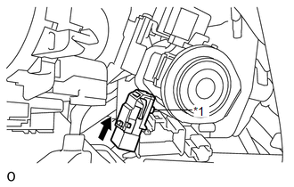
(c) Remove the pin cap.
 Text in Illustration
|
*1 |
Pin Cap |
.png) |
Slide |
(d) Remove the unlock warning switch.
Inspection
INSPECTION
PROCEDURE
1. INSPECT UNLOCK WARNING SWITCH ASSEMBLY
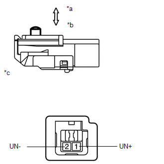
(a) Measure the resistance according to the value(s) in the table below.
Standard Resistance:
|
Tester Connection |
Switch Condition |
Specified Condition |
|---|---|---|
|
1 (UN+) - 2 (UN-) |
Not pushed |
10 kΩ or higher |
|
Pushed |
Below 1 Ω |
If the result is not as specified, replace the unlock warning switch assembly.
Text in Illustration|
*a |
Not pushed |
|
*b |
Pushed |
|
*c |
Component without harness connected (Unlock Warning Switch Assembly) |
Installation
INSTALLATION
PROCEDURE
1. INSTALL UNLOCK WARNING SWITCH ASSEMBLY
(a) If reusing the unlock warning switch assembly:
(1) Install the unlock warning switch.
 Text in Illustration
|
*1 |
Pin Cap |
.png) |
Slide |
(2) Install the pin cap.
|
(3) Connect the unlock warning switch connector. |
|
.png)
(4) Attach the 3 claws to install the cover.
(b) If replacing the unlock warning switch assembly:
(1) While pushing the pin, slide the unlock warning switch to install it.
Text in Illustration|
*1 |
Pin |
|
|
Slide |
|
(2) Connect the unlock warning switch connector. |
|

2. INSTALL WINDSHIELD WIPER SWITCH ASSEMBLY
.gif)
3. INSTALL UPPER STEERING COLUMN COVER
4. INSTALL LOWER STEERING COLUMN COVER
 Transmitter Battery(w/o Smart Key System)
Replacement
REPLACEMENT
CAUTION / NOTICE / HINT
NOTICE:
Take extra care when handling these precision electronic components.
PROCEDURE
1. REMOVE TRANSMITTER HOUSING COVER
(a) Twist ...

Other materials about Toyota 4Runner:
Data List / Active Test
DATA LIST / ACTIVE TEST
1. ACTIVE TEST
HINT:
Using the Techstream to perform Active Tests allows relays, VSVs, actuators and
other items to be operated without removing any parts. This non-intrusive functional
inspection can be very useful because inter ...
Data List / Active Test
DATA LIST / ACTIVE TEST
1. READ DATA LIST
HINT:
Using the Techstream to read the Data List allows the values or states of switches,
sensors, actuators and other items to be read without removing any parts. This non-intrusive
inspection can be very usefu ...
0.0069