Toyota 4Runner: Vehicle Speed Signal Circuit between Stereo Component Amplifier and Combination Meter
DESCRIPTION
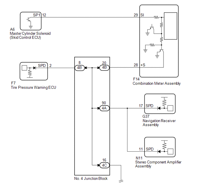
The stereo component amplifier assembly receives a vehicle speed signal from the combination meter assembly to control the ASL function.
HINT:
- A voltage of 12 V or 5 V is output from each ECU and then input to the combination meter assembly. The signal is changed to a pulse signal at the transistor in the combination meter assembly. Each ECU controls the respective systems based on the pulse signal.
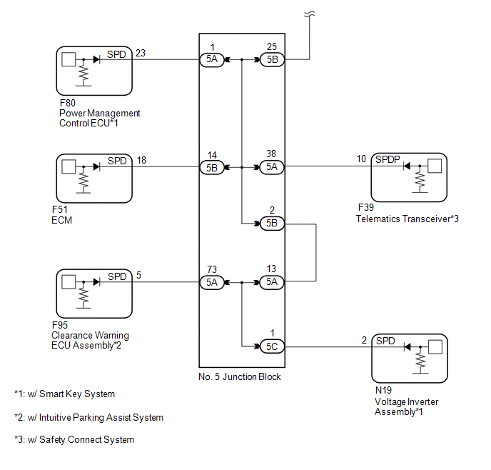
- If a short occurs in any of the ECUs or in the wire harness connected to an ECU, all systems in the diagram below will not operate normally.
WIRING DIAGRAM
PROCEDURE
|
1. |
INSPECT COMBINATION METER ASSEMBLY (OUTPUT WAVEFORM) |
.gif)
| NG | .gif) |
GO TO METER / GAUGE SYSTEM |
|
.gif)
|
2. |
CHECK HARNESS AND CONNECTOR (STEREO COMPONENT AMPLIFIER ASSEMBLY - COMBINATION METER ASSEMBLY) |
(a) Disconnect the N11 stereo component amplifier assembly connector.
(b) Disconnect the F14 combination meter assembly connector.
(c) Measure the resistance according to the value(s) in the table below.
Standard Resistance:
|
Tester Connection |
Condition |
Specified Condition |
|---|---|---|
|
N11-11 (SPD) - F14-28 (+S) |
Always |
Below 1 Ω |
|
N11-11 (SPD) - Body ground |
Always |
10 kΩ or higher |
| OK | |
PROCEED TO NEXT SUSPECTED AREA SHOWN IN PROBLEM SYMPTOMS TABLE |
|
|
3. |
CHECK HARNESS AND CONNECTOR (STEREO COMPONENT AMPLIFIER ASSEMBLY - NO. 4 JUNCTION BLOCK) |
(a) Disconnect the N11 stereo component amplifier assembly connector.
(b) Disconnect the A4 No. 4 junction block connector.
(c) Measure the resistance according to the value(s) in the table below.
Standard Resistance:
|
Tester Connection |
Condition |
Specified Condition |
|---|---|---|
|
N11-11 (SPD) - 4A-90 |
Always |
Below 1 Ω |
|
N11-11 (SPD) - Body ground |
Always |
10 kΩ or higher |
| OK | |
REPAIR OR REPLACE HARNESS OR CONNECTOR (NO. 4 JUNCTION BLOCK) |
| NG | |
REPAIR OR REPLACE HARNESS OR CONNECTOR (STEREO COMPONENT AMPLIFIER ASSEMBLY - NO. 4 JUNCTION BLOCK) |
 AVC-LAN Circuit
DESCRIPTION
Each unit of the navigation system connected to the AVC-LAN (communication bus)
transfers the switch signals using the AVC-LAN.
If a short to +B or short to ground occurs in the AVC-LA ...
 Reverse Signal Circuit
DESCRIPTION
The navigation receiver assembly receives a reverse signal from the park/neutral
position switch assembly.
WIRING DIAGRAM
CAUTION / NOTICE / HINT
NOTICE:
After replacing t ...
Other materials about Toyota 4Runner:
Installation
INSTALLATION
CAUTION / NOTICE / HINT
HINT:
Use the same procedure for both the RH and LH sides.
The procedure listed below is for the LH side.
PROCEDURE
1. INSTALL OUTER REAR VIEW MIRROR ASSEMBLY LH
(a) Attach the claw to install the ou ...
How To Proceed With Troubleshooting
CAUTION / NOTICE / HINT
HINT:
Use the following procedures to troubleshoot the key reminder warning
system.
*: Use the Techstream.
PROCEDURE
1.
VEHICLE BROUGHT TO WORKSHOP
NEXT
...
0.0077