Toyota 4Runner: Voice Recognition Microphone Disconnected (B1579)
DESCRIPTION
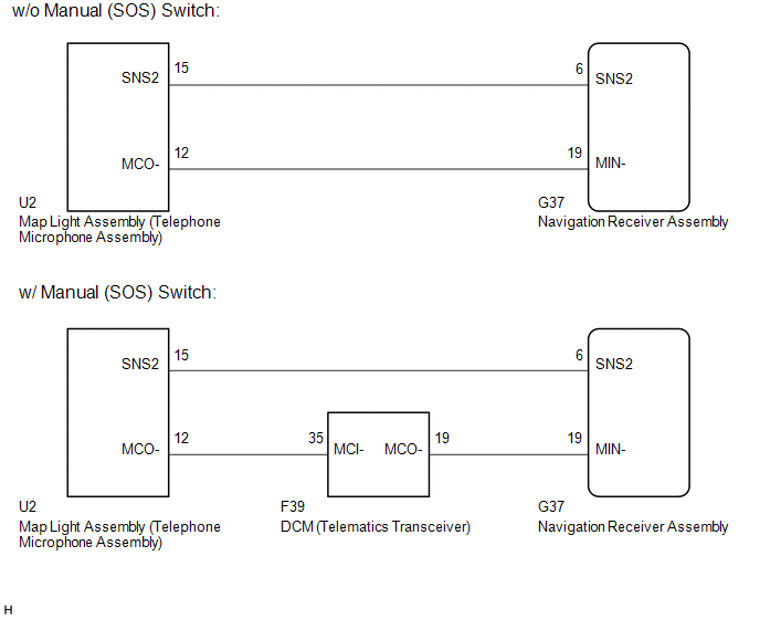
The navigation receiver assembly and map light assembly (telephone microphone assembly) are connected to each other using the microphone connection detection signal lines.
This DTC is stored when a microphone connection detection signal line is disconnected.
|
DTC Code |
DTC Detection Condition |
Trouble Area |
|---|---|---|
|
B1579 |
Telephone microphone signal is lost. |
|
- *1: w/ Manual (SOS) Switch
WIRING DIAGRAM
CAUTION / NOTICE / HINT
NOTICE:
After replacing the navigation receiver assembly of vehicles subscribed to pay-type satellite radio broadcasts, registration of the XM radio ID is necessary.
PROCEDURE
|
1. |
INSPECT NAVIGATION RECEIVER ASSEMBLY |
|
(a) Measure the resistance according to the value(s) in the table below. Standard Resistance:
|
|
| NG | .gif) |
REPLACE NAVIGATION RECEIVER ASSEMBLY |
|
.gif)
|
2. |
CONFIRM MODEL |
(a) Choose the model to be inspected.
|
Model |
Proceed to |
|---|---|
|
w/ Manual (SOS) Switch |
A |
|
w/o Manual (SOS) Switch |
B |
| B | |
GO TO STEP 7 |
|
|
3. |
CHECK HARNESS AND CONNECTOR (DCM (TELEMATICS TRANSCEIVER) - MAP LIGHT ASSEMBLY (TELEPHONE MICROPHONE ASSEMBLY)) |
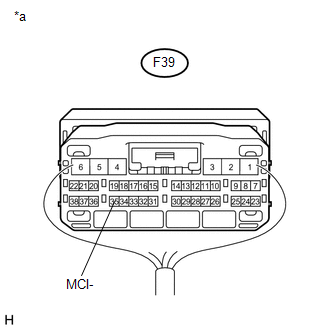
(a) Disconnect the F39 DCM (telematics transceiver) connector.
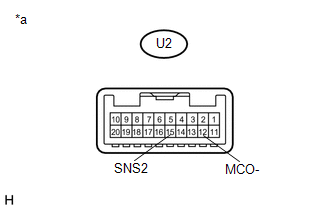
(b) Disconnect the U2 map light assembly (telephone microphone assembly) connector.
(c) Measure the resistance according to the value(s) in the table below.
Standard Resistance:
|
Tester Connection |
Condition |
Specified Condition |
|---|---|---|
|
F39-35 (MCI-) - U2-12 (MCO-) |
Always |
Below 1 Ω |
|
F39-35 (MCI-) - Body ground |
Always |
10 kΩ or higher |
| NG | |
REPAIR OR REPLACE HARNESS OR CONNECTOR |
|
|
4. |
CHECK HARNESS AND CONNECTOR (NAVIGATION RECEIVER ASSEMBLY - DCM (TELEMATICS TRANSCEIVER)) |
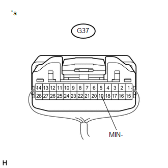
(a) Disconnect the G37 navigation receiver assembly connector.
(b) Disconnect the F39 DCM (telematics transceiver) connector.
(c) Measure the resistance according to the value(s) in the table below.
Standard Resistance:
|
Tester Connection |
Condition |
Specified Condition |
|---|---|---|
|
G37-19 (MIN-) - F39-19 (MCO-) |
Always |
Below 1 Ω |
|
G37-19 (MIN-) - Body ground |
Always |
10 kΩ or higher |
| NG | |
REPAIR OR REPLACE HARNESS OR CONNECTOR |
|
|
5. |
CHECK HARNESS AND CONNECTOR (NAVIGATION RECEIVER ASSEMBLY - MAP LIGHT ASSEMBLY (TELEPHONE MICROPHONE ASSEMBLY)) |
(a) Disconnect the G37 navigation receiver assembly connector.
(b) Disconnect the U2 map light assembly (telephone microphone assembly) connector.
(c) Measure the resistance according to the value(s) in the table below.
Standard Resistance:
|
Tester Connection |
Condition |
Specified Condition |
|---|---|---|
|
G37-6 (SNS2) - U2-15 (SNS2) |
Always |
Below 1 Ω |
|
G37-6 (SNS2) - Body ground |
Always |
10 kΩ or higher |
| NG | |
REPAIR OR REPLACE HARNESS OR CONNECTOR |
|
|
6. |
INSPECT DCM (TELEMATICS TRANSCEIVER) |
(a) Reconnect the F39 DCM (telematics transceiver) connector.
(b) Reconnect the G37 navigation receiver assembly connector.
|
(c) Measure the resistance according to the value(s) in the table below. Standard Resistance:
|
|
(d) Proceed to the next step based on the inspection result.
|
Result |
Proceed to |
|---|---|
|
NG |
A |
|
OK |
B |
|
*a |
Component with harness connected (DCM (Telematics Transceiver)) |
| A | |
REPLACE DCM (TELEMATICS TRANSCEIVER) |
| B | |
GO TO STEP 8 |
|
7. |
CHECK HARNESS AND CONNECTOR (NAVIGATION RECEIVER ASSEMBLY - MAP LIGHT ASSEMBLY (TELEPHONE MICROPHONE ASSEMBLY)) |
(a) Disconnect the G37 navigation receiver assembly connector.
(b) Disconnect the U2 map light assembly (telephone microphone assembly) connector.
(c) Measure the resistance according to the value(s) in the table below.
Standard Resistance:
|
Tester Connection |
Condition |
Specified Condition |
|---|---|---|
|
G37-6 (SNS2) - U2-15 (SNS2) |
Always |
Below 1 Ω |
|
G37-19 (MIN-) - U2-12 (MCO-) |
Always |
Below 1 Ω |
|
G37-6 (SNS2) - Body ground |
Always |
10 kΩ or higher |
|
G37-19 (MIN-) - Body ground |
Always |
10 kΩ or higher |
| NG | |
REPAIR OR REPLACE HARNESS OR CONNECTOR |
|
|
8. |
INSPECT MAP LIGHT ASSEMBLY (TELEPHONE MICROPHONE ASSEMBLY) |
|
(a) Measure the resistance according to the value(s) in the table below. Standard Resistance:
|
|
| OK | |
REPLACE NAVIGATION RECEIVER ASSEMBLY |
| NG | |
REPLACE MAP LIGHT ASSEMBLY (TELEPHONE MICROPHONE ASSEMBLY) |
 HD Radio Tuner Malfunction (B1551,B15A0,B15AD,B15B0,B15B3,B15B4,B15B7)
DESCRIPTION
These DTCs are stored when a malfunction occurs in the navigation receiver assembly.
DTC No.
DTC Detection Condition
Trouble Area
B1551
...
 USB Media Malfunction (B1585)
DESCRIPTION
This DTC is stored when a malfunction occurs in a connected device.
DTC No.
DTC Detection Condition
Trouble Area
B1585
When o ...
Other materials about Toyota 4Runner:
Wireless Door Lock Tuner Circuit Malfunction (B1242)
DESCRIPTION
The door control receiver receives signals from the transmitter and sends these
signals to the main body ECU. This DTC is stored when the applicable RDA signal
cannot be received within 1 second of the PRG signal being output from the main
b ...
Back-up Power Source Circuit
DESCRIPTION
The back-up power source circuit for the air conditioning amplifier assembly
is shown below. Power is supplied even after the ignition switch is turned off and
is used for diagnostic trouble code memory, etc.
WIRING DIAGRAM
CAUTION / NOTIC ...
0.0133