Toyota 4Runner: Washer Nozzle(for Rear Side)
Components
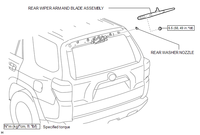
COMPONENTS
ILLUSTRATION
On-vehicle Inspection
ON-VEHICLE INSPECTION
CAUTION / NOTICE / HINT
HINT:
The washer fluid does not spray if the back door and back door glass are not closed.
PROCEDURE
1. INSPECT REAR WASHER NOZZLE
(a) With the engine running, check that the center stream of washer fluid sprays on the windshield within the hatched area shown in the illustration.
Standard:
Washer fluid hits the windshield in the area shown in the illustration.
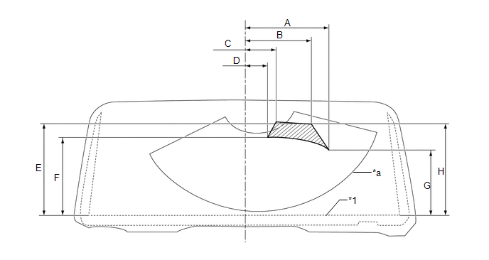 Text in Illustration
|
*1 |
Ceramic Line |
- |
- |
|
*a |
Wiping Pattern |
- |
- |
.png) |
Washer Fluid Spray Area |
- |
- |
Standard:
|
Area |
Measurement |
Area |
Measurement |
|---|---|---|---|
|
A |
300.8 mm (11.8 in.) |
B |
235.1 mm (9.26 in.) |
|
C |
110.8 mm (4.36 in.) |
D |
81 mm (3.19 in.) |
|
E |
328.8 mm (12.9 in.) |
F |
278.2 mm (10.9 in.) |
|
G |
230.7 mm (9.08 in.) |
H |
322.7 mm (12.7 in.) |
If the result is not as specified, replace the malfunctioning rear washer nozzle.
Removal
REMOVAL
PROCEDURE
1. REMOVE REAR SPOILER SUB-ASSEMBLY
(a) Remove the rear spoiler sub-assembly (See page
.gif) ).
).
2. REMOVE REAR WIPER ARM AND BLADE ASSEMBLY
3. REMOVE REAR WASHER NOZZLE
|
(a) Detach the 2 claws. |
|
|
(b) Disconnect the washer hose and remove the rear washer nozzle. |
|
Adjustment
ADJUSTMENT
PROCEDURE
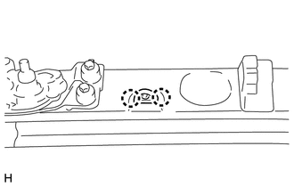
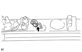
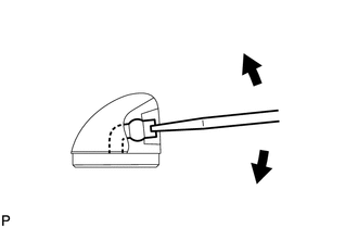
1. ADJUST REAR WASHER NOZZLE
|
(a) Using a screwdriver, adjust the direction of the rear washer nozzle. HINT: Use a thin-bladed screwdriver with a tip approximately 1 mm (0.0394 in.) thick. NOTICE: Do not use a safety pin or other pointed tools. Doing so may damage the inside of the washer nozzle. |
|
Installation
INSTALLATION
PROCEDURE
1. INSTALL REAR WASHER NOZZLE
|
(a) Connect the washer hose. |
|
.png)
|
(b) Attach the 2 claws to install the rear washer nozzle. |
|
.png)
2. INSPECT REAR WASHER NOZZLE
.gif)
3. ADJUST REAR WASHER NOZZLE
4. INSTALL REAR WIPER ARM AND BLADE ASSEMBLY
5. INSTALL REAR SPOILER SUB-ASSEMBLY
(a) Install the rear spoiler sub-assembly (See page
).
 Washer Nozzle(for Front Side)
Components
COMPONENTS
ILLUSTRATION
On-vehicle Inspection
ON-VEHICLE INSPECTION
PROCEDURE
1. INSPECT WASHER NOZZLE SUB-ASSEMBLY
(a) With the engine running, check the position that the was ...

Other materials about Toyota 4Runner:
Inspection
INSPECTION
PROCEDURE
1. INSPECT REAR NO. 1 SEAT OUTER BELT ASSEMBLY
(a) Check the ELR.
(1) When the inclination of the retractor is 15° or less, check that
the belt can be pulled from the retractor. When the inclination of the retractor
...
Combination Meter
Components
COMPONENTS
ILLUSTRATION
ILLUSTRATION
ILLUSTRATION
Removal
REMOVAL
PROCEDURE
1. DISCONNECT CABLE FROM NEGATIVE BATTERY TERMINAL
CAUTION:
Wait at least 90 seconds after disconnecting the cable from the negative (-)
battery termin ...
0.0068