Toyota 4Runner: BUS IC Communication Malfunction (B1497/97)
DESCRIPTION
The air conditioning harness assembly connects the No. 1 air conditioning amplifier assembly and each servo motor. The No. 1 air conditioning amplifier assembly supplies power and sends operation instructions to each servo motor through the air conditioning harness assembly. Each servo motor sends the damper position information to the No. 1 air conditioning amplifier assembly.
|
DTC Code |
DTC Detection Condition |
Trouble Area |
|---|---|---|
|
B1497/97 |
An open circuit or malfunction in the communication line. |
|
WIRING DIAGRAM

PROCEDURE
|
1. |
CHECK NO. 1 AIR CONDITIONING AMPLIFIER ASSEMBLY |
|
(a) Remove the No. 1 air conditioning amplifier assembly with its connectors
still connected (See page |
|
.gif) ).
).
(b) Measure the resistance according to the value(s) in the table below.
Standard Resistance:
|
Tester Connection |
Condition |
Specified Condition |
|---|---|---|
|
z15-2 (BUS G) - Body ground |
Always |
Below 1 Ω |
(c) Measure the voltage according to the value(s) in the table below.
Standard Voltage:
|
Tester Connection |
Switch Condition |
Specified Condition |
|---|---|---|
|
z15-2 (BUS G) - z15-4 (B BUS) |
Always |
11 to 14 V |
|
z15-2 (BUS G) - z15-3 (BUS) |
Ignition switch ON |
Pulse generation |
|
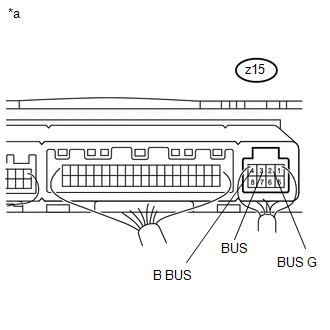
*a |
Component with harness connected (No. 1 Air Conditioning Amplifier Assembly) |
|
Result |
Proceed to |
|---|---|
|
OK (When troubleshooting according to problem symptoms table) |
A |
|
OK (When troubleshooting according to the DTC) |
B |
|
NG |
C |
| A | .gif) |
PROCEED TO NEXT SUSPECTED AREA SHOWN IN PROBLEM SYMPTOMS TABLE |
| B | |
REPLACE AIR CONDITIONING HARNESS ASSEMBLY |
| C | |
REPLACE NO. 1 AIR CONDITIONING AMPLIFIER ASSEMBLY |
 Air Mix Damper Control Servo Motor Circuit (Driver Side) (B1446/46)
DESCRIPTION
The damper servo sub-assembly (driver side air mix damper servo) sends pulse
signals to inform the No. 1 air conditioning amplifier assembly of the damper position.
The No. 1 air cond ...
 Air Conditioning Control Panel Circuit
DESCRIPTION
This circuit consists of the heater control assembly and air conditioning amplifier
assembly. When the heater control assembly is operated, signals are transmitted
to the air conditio ...
Other materials about Toyota 4Runner:
GPS Mark is not Displayed
CAUTION / NOTICE / HINT
NOTICE:
After replacing the navigation receiver assembly of vehicles subscribed to pay-type
satellite radio broadcasts, registration of the XM radio ID is necessary.
PROCEDURE
1.
CHECK CABIN
(a) Ch ...
Headlight Dimmer Switch Circuit
DESCRIPTION
The main body ECU receives the following signals:
Headlight dimmer switch tail, head, AUTO*, high or high flash signal
Front fog light switch signal
*: w/ Automatic Light Control System
WIRING DIAGRAM
PROCEDU ...

0.0272