Toyota 4Runner: Clearance Sonar Main Switch
Components
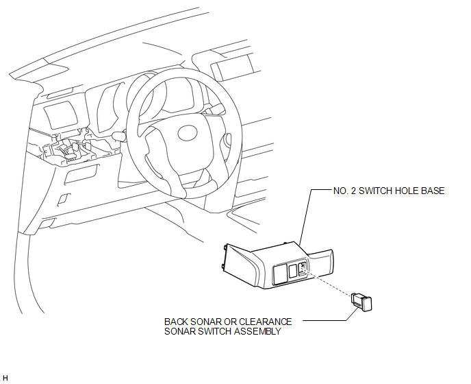
COMPONENTS
ILLUSTRATION
Removal
REMOVAL
PROCEDURE
1. REMOVE NO. 2 SWITCH HOLE BASE
.gif)
2. REMOVE BACK SONAR OR CLEARANCE SONAR SWITCH ASSEMBLY
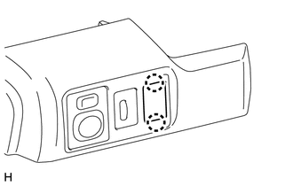
(a) Detach the 2 claws and remove the back sonar or clearance sonar switch.
Inspection
INSPECTION
PROCEDURE
1. INSPECT BACK SONAR OR CLEARANCE SONAR SWITCH ASSEMBLY
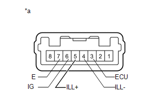
(a) Check the resistance.
(1) Measure the resistance according to the value(s) in the table below.
Standard Resistance:
|
Tester Connection |
Switch Condition |
Specified Condition |
|---|---|---|
|
3 (ECU) - 6 (IG) |
Sonar switch off |
10 kΩ or higher |
|
Sonar switch on |
Below 1 Ω |
If the result is not as specified, replace the back sonar or clearance sonar switch assembly.
(b) Apply battery voltage to the connector and check the LED illumination condition.
OK:
|
Measurement Condition |
Specified Condition |
|---|---|
|
Battery positive (+) → Terminal 3 (ECU) Battery negative (-) → Terminal 7 (E) |
LED illuminates |
|
Battery positive (+) → Terminal 5 (ILL+) Battery negative (-) → Terminal 4 (ILL-) |
LED illuminates |
If the result is not as specified, replace the back sonar or clearance sonar switch assembly.
Text in Illustration|
*a |
Component without harness connected (Back Sonar or Clearance Sonar Switch Assembly) |
Installation
INSTALLATION
PROCEDURE
1. INSTALL BACK SONAR OR CLEARANCE SONAR SWITCH ASSEMBLY
(a) Attach the 2 claws to install the back sonar or clearance sonar switch.
2. INSTALL NO. 2 SWITCH HOLE BASE
.gif)

 Clearance Warning Buzzer
Components
COMPONENTS
ILLUSTRATION
Removal
REMOVAL
PROCEDURE
1. REMOVE INSTRUMENT PANEL SUB-ASSEMBLY
(a) Remove the instrument panel sub-assembly (See page
).
2. REMOVE NO. 1 CLEARANCE ...
Other materials about Toyota 4Runner:
Short to GND in Motor LH Circuit (21,23)
DESCRIPTION
When there is a short to GND in the side auto step motor circuit, the side auto
step controller ECU assembly does not operate the automatic running board.
DTC No.
Detection Condition
Trouble Area
...
Definition Of Terms
DEFINITION OF TERMS
Term
Definition
Monitor description
Description of what the ECM monitors and how it detects malfunctions
(monitoring purpose and its details).
Related DTCs
G ...

0.0067