Toyota 4Runner: Downhill Assist Control Switch Malfunction (Test Mode DTC) (C1379)
DESCRIPTION
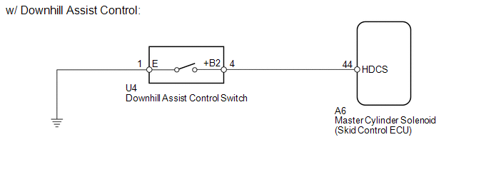
w/ Downhill Assist Control:
DTC C1379 is cleared when the downhill assist control switch sends a downhill assist control operation signal or when test mode ends.
w/ Crawl Control:
DTC C1379 is cleared when the crawl control switch sends a crawl control operation signal or when test mode ends.
|
DTC Code |
DTC Detection Condition |
Trouble Area |
|---|---|---|
|
C1379 |
Stored only during test mode. |
|
WIRING DIAGRAM
CAUTION / NOTICE / HINT
NOTICE:
- When replacing the master cylinder solenoid, perform calibration (See
page
.gif) ).
). - Inspect the fuses for circuits related to this system before performing the following inspection procedure.
PROCEDURE
|
1. |
CONFIRM VEHICLE SPECIFICATIONS |
(a) Confirm the vehicle specifications.
Result|
Result |
Proceed to |
|---|---|
|
w/ Downhill Assist Control |
A |
|
w/ Crawl Control |
B |
| B | .gif) |
GO TO STEP 6 |
|
.gif)
|
2. |
READ VALUE USING TECHSTREAM (DOWNHILL ASSIST CONTROL SW) |
(a) Turn the ignition switch off.
(b) Connect the Techstream to the DLC3.
(c) Turn the ignition switch to ON.
(d) Turn the Techstream on.
(e) Enter the following menus: Chassis / ABS/VSC/TRAC / Data List.
(f) Check the Data List for proper functioning of the downhill assist control switch.
ABS/VSC/TRAC|
Tester Display |
Measurement Item/Range |
Normal Condition |
Diagnostic Note |
|---|---|---|---|
|
Downhill Assist Control SW |
Downhill assist control switch / ON or OFF |
ON: Downhill assist control on OFF: Downhill assist control off |
- |
OK:
The Techstream displays ON or OFF according to downhill assist control switch operation.
| NG | |
GO TO STEP 4 |
|
|
3. |
CHECK TEST MODE DTC |
(a) Perform the Downhill Assist Control Switch Check in the Test Mode Procedure
(See page ).
OK:
Test mode DTC C1379 is cleared.
| OK | |
USE SIMULATION METHOD TO CHECK |
| NG | |
REPLACE MASTER CYLINDER SOLENOID |
|
4. |
INSPECT DOWNHILL ASSIST CONTROL SWITCH |
| NG | |
REPLACE DOWNHILL ASSIST CONTROL SWITCH |
|
|
5. |
CHECK HARNESS AND CONNECTOR (SKID CONTROL ECU - DOWNHILL ASSIST CONTROL SWITCH/BODY GROUND) |
(a) Disconnect the A6 skid control ECU connector.
(b) Disconnect the U4 downhill assist control switch connector.
(c) Measure the resistance according to the value(s) in the table below.
Standard Resistance:
|
Tester Connection |
Condition |
Specified Condition |
|---|---|---|
|
A6-44 (HDCS) - U4-4 (+B2) |
Always |
Below 1 Ω |
|
A6-44 (HDCS) - Body ground |
Always |
10 kΩ or higher |
|
U4-1 (E) - Body ground |
Always |
Below 1 Ω |
| OK | |
REPLACE MASTER CYLINDER SOLENOID |
| NG | |
REPAIR OR REPLACE HARNESS OR CONNECTOR |
|
6. |
CHECK CAN BUS |
(a) Check that there are no problems with the CAN communication system (See page
).
| NG | |
GO TO CAN COMMUNICATION SYSTEM (HOW TO PROCEED WITH TROUBLESHOOTING) |
|
|
7. |
READ VALUE USING TECHSTREAM (CRAWL CONTROL MODE SELECT SWITCH) |
(a) Turn the ignition switch off.
(b) Connect the Techstream to the DLC3.
(c) Turn the ignition switch to ON.
(d) Turn the Techstream on.
(e) Enter the following menus: Body Electrical / D-SEAT SW / Data List.
(f) Check the Data List for proper functioning of the crawl control mode select switch.
D-SEAT SW|
Tester Display |
Measurement Item/Range |
Normal Condition |
Diagnostic Note |
|---|---|---|---|
|
Crawl Control Main Switch |
Crawl control switch (ON/OFF switch)/ ON or OFF |
ON: Crawl control on OFF: Crawl control off |
- |
OK:
The Techstream displays ON or OFF according to crawl switch operation.
| NG | |
GO TO STEP 10 |
|
|
8. |
READ VALUE USING TECHSTREAM (CRAWL CONTROL SWITCH) |
(a) Turn the ignition switch off.
(b) Connect the Techstream to the DLC3.
(c) Turn the ignition switch to ON.
(d) Turn the Techstream on.
(e) Enter the following menus: Chassis / ABS/VSC/TRAC / Data List.
(f) Check the Data List for proper functioning of the crawl control switch.
ABS/VSC/TRAC|
Tester Display |
Measurement Item/Range |
Normal Condition |
Diagnostic Note |
|---|---|---|---|
|
Crawl Control Switch |
Crawl switch (mode select switch)/ LOW, MIDLOW, MID, MIDHIGH or HIGH |
Actual crawl speed selector switch position |
- |
OK:
The Techstream displays LOW, MIDLOW, MID, MIDHIGH or HIGH according to crawl switch (mode selector switch) operation.
| NG | |
GO TO STEP 11 |
|
|
9. |
CHECK TEST MODE DTC |
(a) Perform the crawl switch check in the Test Mode Procedure (See page
).
OK:
Test mode DTC C1379 is cleared.
| OK | |
USE SIMULATION METHOD TO CHECK |
| NG | |
REPLACE MASTER CYLINDER SOLENOID |
|
10. |
CHECK TERMINAL VOLTAGE AND RESISTANCE (IG, +B, GND) |
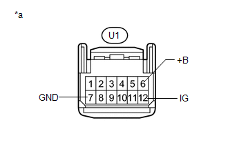
(a) Disconnect the U1 drive monitor switch connector.
|
(b) Measure the voltage according to the value(s) in the table below. Standard Voltage:
|
|
(c) Measure the resistance according to the value(s) in the table below.
Standard Resistance:
|
Tester Connection |
Condition |
Specified Condition |
|---|---|---|
|
U1-7 (GND) - Body ground |
Always |
Below 1 Ω |
|
*a |
Front view of wire harness connector (to Drive Monitor Switch) |
| OK | |
REPLACE DRIVE MONITOR SWITCH |
| NG | |
REPAIR OR REPLACE HARNESS OR CONNECTOR |
|
11. |
REPLACE DRIVE MONITOR SWITCH |
(a) Replace the drive monitor switch (See page
).
|
|
12. |
CHECK TEST MODE DTC |
(a) Perform the crawl switch check in the Test Mode Procedure (See page
).
OK:
Test mode DTC C1379 is cleared.
| OK | |
END |
| NG | |
REPLACE MASTER CYLINDER SOLENOID |
 Diameter of the Tire is not Uniform (C1337)
DESCRIPTION
The skid control ECU measures the speed of each wheel by receiving signals from
the speed sensors. These signals are used for recognizing that all 4 wheels are
operating properly. The ...
 Stop Light Control Relay Malfunction (C1380)
DESCRIPTION
Upon receiving the hill-start assist control operating signal from the master
cylinder solenoid (skid control ECU), the Stop light control relay (Stop light switch
assembly) contact t ...
Other materials about Toyota 4Runner:
Screen Flicker or Color Distortion
PROCEDURE
1.
CHECK DISPLAY SETTING
(a) Reset display settings (contrast, brightness) and check that the screen appears
normal.
OK:
The display returns to normal.
OK
END
NG
...
Terminals Of Ecu
TERMINALS OF ECU
1. CHECK DRIVER SIDE JUNCTION BLOCK ASSEMBLY AND MAIN BODY ECU (MULTIPLEX NETWORK
BODY ECU)
(a) Remove the main body ECU (multiplex network body ECU) (See page
).
(b) Measure the voltage and resistance according to the value(s) in the ...

0.0069