Toyota 4Runner: Front Airbag Sensor LH Malfunction (B1615/14)
DESCRIPTION
The front airbag sensor LH consists of the diagnostic circuit and frontal deceleration sensor, etc.
If the center airbag sensor receives signals from the frontal deceleration sensor, it determines whether the SRS should be activated.
DTC B1615/14 is stored when a malfunction is detected in the front airbag sensor LH circuit.
|
DTC Code |
DTC Detection Condition |
Trouble Area |
|---|---|---|
|
B1615/14 |
Either condition is met:
|
|
WIRING DIAGRAM
.png)
CAUTION / NOTICE / HINT
NOTICE:
When disconnecting the cable from the negative (-) battery terminal while performing
repairs, some systems need to be initialized after the cable is reconnected (See
page .gif) ).
).
PROCEDURE
|
1. |
CHECK FRONT AIRBAG SENSOR LH |
(a) Turn the ignition switch off.
(b) Disconnect the cable from the negative (-) battery terminal, and wait for at least 90 seconds.
(c) Interchange the front airbag sensor RH with LH and connect the connectors to them.
(d) Connect the cable to the negative (-) battery terminal, and wait for at least 2 seconds.
(e) Turn the ignition switch to ON, and wait for at least 60 seconds.
(f) Clear the DTCs stored in memory (See page
).
(g) Turn the ignition switch off.
(h) Turn the ignition switch to ON, and wait for at least 60 seconds.
(i) Check for DTCs (See page ).
Result
|
Result |
Proceed to |
|---|---|
|
DTC B1615 is output |
A |
|
DTC B1610 is output |
B |
|
DTC B1610 and B1615 are not output |
C |
HINT:
Codes other than DTC B1610 and B1615 may be output at this time, but they are not related to this check.
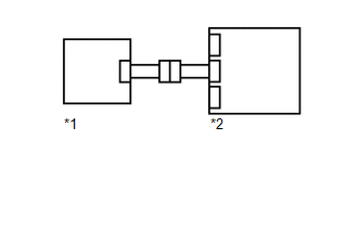
Text in Illustration|
*1 |
Front Airbag Sensor RH |
|
*2 |
Center Airbag Sensor |
| C | .gif) |
USE SIMULATION METHOD TO CHECK |
| A | |
REPLACE CENTER AIRBAG SENSOR ASSEMBLY |
| B | |
REPLACE FRONT AIRBAG SENSOR LH |
 Lost Communication with Front Airbag Sensor RH (B1612/83,B1613/83)
DESCRIPTION
The front airbag sensor RH circuit consists of the center airbag sensor and front
airbag sensor RH.
The front airbag sensor RH detects impacts to the vehicle and sends signals to
the ...
 Center Airbag Sensor Assembly Malfunction (B1000/31)
DESCRIPTION
The center airbag sensor assembly consists of a deceleration sensor, safing sensor,
drive circuit, diagnosis circuit, ignition control, etc.
If the center airbag sensor assembly receiv ...
Other materials about Toyota 4Runner:
Components
COMPONENTS
ILLUSTRATION
ILLUSTRATION
ILLUSTRATION
ILLUSTRATION
ILLUSTRATION
...
Dtc Check / Clear
DTC CHECK / CLEAR
1. CHECK DTC
(a) Connect the Techstream to the DLC3.
(b) Turn the engine switch on (IG).
(c) Turn the Techstream on.
(d) Enter the following menus: Body Electrical / Smart Key / Trouble Codes.
(e) Check for DTCs.
2. CLEAR DTC
(a) Conn ...

0.0075