Toyota 4Runner: LVDS Signal Malfunction (from Extension Module) (B1532)
DESCRIPTION
|
DTC No. |
DTC Detection Condition |
Trouble Area |
|---|---|---|
|
B1532 |
When one of the conditions below is met:
|
|
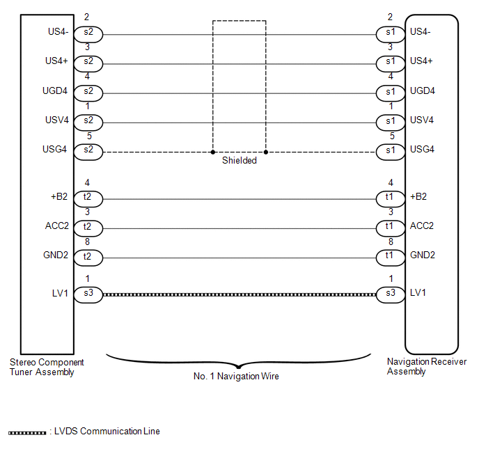
WIRING DIAGRAM
CAUTION / NOTICE / HINT
NOTICE:
After replacing the navigation receiver assembly of vehicles subscribed to pay-type satellite radio broadcasts, registration of the XM radio ID is necessary.
PROCEDURE
|
1. |
CHECK DTC |
(a) Clear the DTCs (See page .gif) ).
).
(b) Recheck for DTCs and check if the same DTC are output again.
OK:
No DTCs are output.
| OK | .gif) |
USE SIMULATION METHOD TO CHECK |
|
.gif)
|
2. |
CHECK HARNESS AND CONNECTOR (NAVIGATION RECEIVER ASSEMBLY - STEREO COMPONENT TUNER ASSEMBLY) |
(a) Disconnect the s1 and t1 navigation receiver assembly connectors.
(b) Disconnect the s2 and t2 stereo component tuner assembly connector.
(c) Measure the resistance according to the value(s) in the table below.
Standard Resistance:
|
Tester Connection |
Condition |
Specified Condition |
|---|---|---|
|
s1-1 (USV4) - s2-1 (USV4) |
Always |
Below 1 Ω |
|
s1-2 (US4-) - s2-2 (US4-) |
Always |
Below 1 Ω |
|
s1-3 (US4+) - s2-3 (US4+) |
Always |
Below 1 Ω |
|
s1-4 (UGD4) - s2-4 (UGD4) |
Always |
Below 1 Ω |
|
s1-5 (USG4) - s2-5 (USG4) |
Always |
Below 1 Ω |
|
t1-4 (+B2) - t2-4 (+B2) |
Always |
Below 1 Ω |
|
t1-3 (ACC2) - t2-3 (ACC2) |
Always |
Below 1 Ω |
|
t1-8 (GND2) - t2-8 (GND2) |
Always |
Below 1 Ω |
|
s1-1 (USV4) - Body ground |
Always |
10 kΩ or higher |
|
s1-2 (US4-) - Body ground |
Always |
10 kΩ or higher |
|
s1-3 (US4+) - Body ground |
Always |
10 kΩ or higher |
|
s1-4 (UGD4) - Body ground |
Always |
10 kΩ or higher |
|
s1-5 (USG4) - Body ground |
Always |
10 kΩ or higher |
|
t1-4 (+B2) - Body ground |
Always |
10 kΩ or higher |
|
t1-3 (ACC2) - Body ground |
Always |
10 kΩ or higher |
|
t1-8 (GND2) - Body ground |
Always |
10 kΩ or higher |
| NG | |
REPAIR OR REPLACE HARNESS AND CONNECTOR |
|
|
3. |
REPLACE HARNESS AND CONNECTOR (LVDS COMMUNICATION LINE) |
(a) Replace the harness and connector (LVDS communication line).
(b) Clear the DTCs (See page ).
(c) Recheck for DTCs and check if the same DTC are output again.
OK:
No DTCs are output.
| OK | |
END |
|
|
4. |
REPLACE STEREO COMPONENT TUNER ASSEMBLY |
(a) Replace the stereo component tuner assembly (See page
).
(b) Clear the DTCs (See page ).
(c) Recheck for DTCs and check if the same DTC are output again.
OK:
No DTCs are output.
| OK | |
END |
| NG | |
REPLACE NAVIGATION RECEIVER ASSEMBLY |
 Diagnostic Trouble Code Chart
DIAGNOSTIC TROUBLE CODE CHART
Navigation System
DTC Code
Detection Item
See page
B1532
LVDS Signal Malfunction (from Extension Module)
...
 HD Radio Tuner Malfunction (B1551,B15A0,B15AD,B15B0,B15B3,B15B4,B15B7)
DESCRIPTION
These DTCs are stored when a malfunction occurs in the navigation receiver assembly.
DTC No.
DTC Detection Condition
Trouble Area
B1551
...
Other materials about Toyota 4Runner:
Installation
INSTALLATION
PROCEDURE
1. INSTALL STEREO COMPONENT TUNER ASSEMBLY
(a) Connect the 6 connectors to the radio and display receiver assembly or navigation
receiver assembly and stereo component tuner assembly.
HINT:
Connect the connectors with white tape t ...
Removal
REMOVAL
CAUTION / NOTICE / HINT
CAUTION:
Wear protective gloves. Sharp areas on the parts may injure your hands.
HINT:
The procedure listed below is for the RH side.
PROCEDURE
1. PRECAUTION
CAUTION:
Be sure to read Precaution thoroughly before ...

0.0071