Toyota 4Runner: Open or Short in Front Speed Sensor RH Circuit (C1405,C1406)
DESCRIPTION
Refer to DTCs C1401 and C1402 (See page .gif) ).
).
|
DTC Code |
DTC Detection Condition |
Trouble Area |
|---|---|---|
|
C1405 C1406 |
Either condition is met:
|
|
HINT:
- DTC C1405 is for the front speed sensor RH.
- DTC C1406 is for the front speed sensor LH.
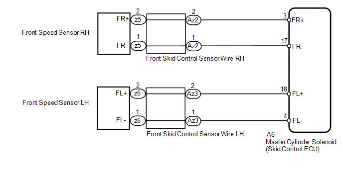
WIRING DIAGRAM
CAUTION / NOTICE / HINT
NOTICE:
- When replacing the master cylinder solenoid, perform calibration (See
page ).
- Check the speed sensor signal after replacement (See page
).
PROCEDURE
|
1. |
CHECK HARNESS AND CONNECTOR (MOMENTARY INTERRUPTION) |
(a) Using the Techstream, check for any momentary interruption in the wire harness
and connector corresponding to the DTC (See page
).
|
Tester Display |
Measurement Item/Range |
Normal Condition |
Diagnostic Note |
|---|---|---|---|
|
FR Speed Open |
Front speed sensor RH open detection/ Error or Normal |
Normal |
- |
|
FL Speed Open |
Front speed sensor LH open detection/ Error or Normal |
Normal |
- |
OK:
Normal (there are no momentary interruptions).
HINT:
Perform the above inspection before removing the sensor and connector.
| NG | .gif) |
GO TO STEP 4 |
|
.gif)
|
2. |
READ VALUE USING TECHSTREAM (FRONT SPEED SENSOR) |
| NG | |
GO TO STEP 4 |
|
|
3. |
RECONFIRM DTC |
(a) Clear the DTCs (See page ).
(b) Turn the ignition switch off.
(c) Start the engine.
(d) Drive the vehicle at a speed of 40 km/h (25 mph) or more for at least 60 seconds.
(e) Check if the same DTC is output (See page
).
|
Result |
Proceed to |
|---|---|
|
DTCs C1405 and C1406 are not output |
A |
|
DTCs C1405 and/or C1406 are output |
B |
| A | |
USE SIMULATION METHOD TO CHECK |
| B | |
REPLACE MASTER CYLINDER SOLENOID |
|
4. |
INSPECT SKID CONTROL SENSOR WIRE |
(a) Remove the skid control sensor wire (See page
).
|
(b) Measure the resistance according to the value(s) in the table below. Standard Resistance: for RH
|
|
| NG | |
REPLACE SKID CONTROL SENSOR WIRE |
|
|
5. |
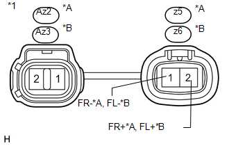
CHECK HARNESS AND CONNECTOR (SKID CONTROL ECU - FRONT SPEED SENSOR) |
(a) Install the skid control sensor wire.
(b) Disconnect the A6 skid control ECU connector.
(c) Disconnect the z5 and/or z6 front speed sensor connector.
(d) Measure the resistance according to the value(s) in the table below.
Standard Resistance:
for RH|
Tester Connection |
Condition |
Specified Condition |
|---|---|---|
|
A6-3 (FR+) - z5-2 (FR+) |
Always |
Below 1 Ω |
|
A6-3 (FR+) - Body ground |
Always |
10 kΩ or higher |
|
A6-17 (FR-) - z5-1 (FR-) |
Always |
Below 1 Ω |
|
A6-17 (FR-) - Body ground |
Always |
10 kΩ or higher |
|
Tester Connection |
Condition |
Specified Condition |
|---|---|---|
|
A6-18 (FL+) - z6-2 (FL+) |
Always |
Below 1 Ω |
|
A6-18 (FL+) - Body ground |
Always |
10 kΩ or higher |
|
A6-4 (FL-) - z6-1 (FL-) |
Always |
Below 1 Ω |
|
A6-4 (FL-) - Body ground |
Always |
10 kΩ or higher |
| NG | |
REPAIR OR REPLACE HARNESS OR CONNECTOR |
|
|
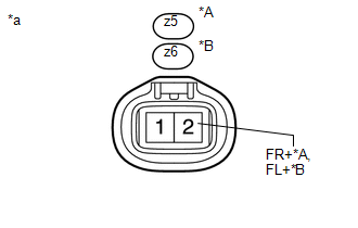
6. |
CHECK TERMINAL VOLTAGE (FR+, FL+) |
(a) Disconnect the z5 and/or z6 front speed sensor connector.
(b) Connect the A6 skid control ECU connector.
|
(c) Measure the voltage according to the value(s) in the table below. Standard Voltage: for RH
|
|
| OK | |
REPLACE FRONT SPEED SENSOR |
| NG | |
REPLACE MASTER CYLINDER SOLENOID |
 Rear Speed Sensor RH Malfunction (C1403,C1273,C1274,C1404)
DESCRIPTION
Refer to DTCs C1401 and C1402 (See page ).
DTC Code
DTC Detection Condition
Trouble Area
C1403
C1404
One of the following ...
 Open or Short in Rear Speed Sensor RH Circuit (C1407,C1408)
DESCRIPTION
Refer to DTCs C1401 and C1402 (See page ).
DTC Code
DTC Detection Condition
Trouble Area
C1407
C1408
Either condition is ...
Other materials about Toyota 4Runner:
Removal
REMOVAL
PROCEDURE
1. DRAIN ENGINE COOLANT
(a) Drain engine coolant (See page ).
2. RECOVER REFRIGERANT FROM REFRIGERATION SYSTEM
3. DISCONNECT CABLE FROM NEGATIVE BATTERY TERMINAL
CAUTION:
Wait at least 90 seconds after disconnecting the cable from ...
Audio Receiver Assembly Communication Stop Mode
DESCRIPTION
Detection Item
Symptom
Trouble Area
Audio Receiver Assembly Communication Stop Mode
Either condition is met:
"Display and Navigation (AVN1)" is not displayed on t ...
0.0105