
Toyota 4Runner: Parts Location
Toyota 4Runner Service Manual / Audio / Visual / Telematics / Garage Door Opener / Garage Door Opener System / Parts Location
PARTS LOCATION
ILLUSTRATION
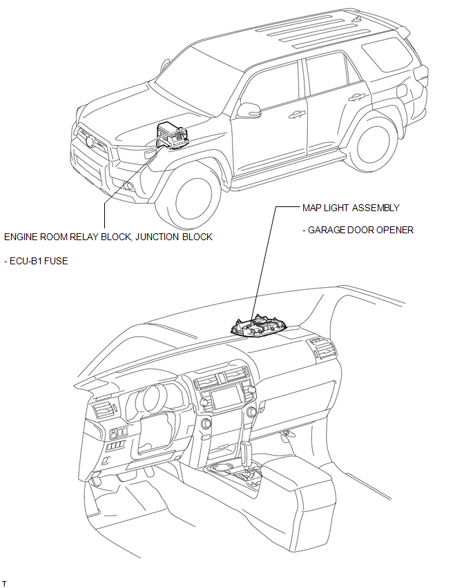

 System Diagram
SYSTEM DIAGRAM
...
Other materials about Toyota 4Runner:
Door Side Airbag Sensor RH Malfunction (B1690/15,B1695/16)
DESCRIPTION
The side airbag sensor LH or RH consists of the safing sensor, diagnostic circuit,
lateral deceleration sensor, etc.
If the center airbag sensor receives signals from the lateral deceleration sensor,
it determines whether the SRS should be ac ...
Rear Clearance Sonar Sensor RH Circuit
DESCRIPTION
The ultrasonic sensor sends and receives ultrasonic waves. Based on the received
wave, the sensor calculates the approximate distance between the vehicle and the
obstacle, and sends the distance value as a signal to the clearance warning ECU
...
© 2016-2026 | www.to4runner.net

0.0069
0.0069