Toyota 4Runner: Rear Speed Sensor
Components
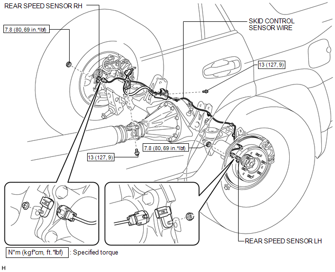
COMPONENTS
ILLUSTRATION
Removal
REMOVAL
PROCEDURE
1. REMOVE REAR WHEEL
2. REMOVE REAR SPEED SENSOR LH
|
(a) Disconnect the speed sensor connector. |
|
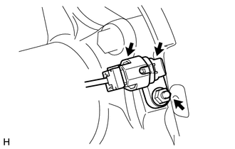
(b) Remove the nut and speed sensor.
NOTICE:
Pull out the sensor while trying as much as possible not to rotate it.
3. REMOVE REAR SPEED SENSOR RH
HINT:
Use the same procedure described for the LH side.
4. REMOVE SKID CONTROL SENSOR WIRE
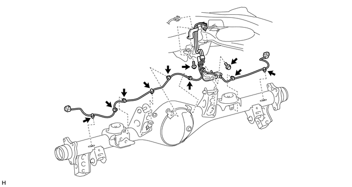
(a) Disconnect the connector.
(b) Detach the connector.
(c) Detach the 8 clamps.
(d) Remove the 2 bolts and 2 sensor clamps.
Inspection
INSPECTION
PROCEDURE
1. CHECK REAR SPEED SENSOR
(a) Check the sensor.
Under any of the following conditions, replace the sensor with a new one:
- The surface of the sensor is cracked, dented or chipped.
- The connector is scratched, cracked or damaged.
- The sensor has been dropped.
Installation
INSTALLATION
PROCEDURE
1. INSTALL SKID CONTROL SENSOR WIRE
(a) Install the 2 sensor clamps with the 2 bolts.
Torque:
13 N·m {127 kgf·cm, 9 ft·lbf}
NOTICE:
Make sure the clamp rotation stopper touches the installation position.
(b) Connect the connector.
NOTICE:
Securely connect the connector.
(c) Attach the connector.
(d) Attach the 8 clamps.
NOTICE:
When attaching the clamps, do not twist the wire harness.
2. INSTALL REAR SPEED SENSOR LH
(a) Install the speed sensor with the nut.
Torque:
7.8 N·m {80 kgf·cm, 69 in·lbf}
NOTICE:
- Make sure there are no pieces of iron or other foreign matter attached to the sensor tip.
- While inserting the speed sensor into the axle hole, do not strike or damage the sensor tip.
- After installing the speed sensor, make sure there is no clearance or foreign matter between the sensor stay part and the axle.
- Make sure there is no foreign matter attached to the speed sensor rotor.
(b) Connect the speed sensor connector.
NOTICE:
Securely connect the connector.
3. INSTALL REAR SPEED SENSOR RH
HINT:
Use the same procedure described for the LH side.
4. INSTALL REAR WHEEL
.gif)
5. CHECK SPEED SENSOR SIGNAL
(a) Check the speed sensor signal (See page
).
 Front Speed Sensor
Components
COMPONENTS
ILLUSTRATION
Removal
REMOVAL
CAUTION / NOTICE / HINT
HINT:
The procedure listed below is for the LH side.
Other than areas where instructions are provide ...
 Relay
Relay
On-vehicle Inspection
ON-VEHICLE INSPECTION
PROCEDURE
1. CHECK STOP LIGHT CONTROL RELAY
(a) Remove the stop light control relay from the engine room relay block.
(b) Measure the resi ...
Other materials about Toyota 4Runner:
Pressure Control Solenoid "B" Electrical (Shift Solenoid Valve SL2) (P0778)
DESCRIPTION
Shifting from 1st to 5th is performed in combination with the ON and OFF operation
of the shift solenoid valves SL1, SL2, S1, S2 and SR, which are controlled by the
ECM. If an open or short circuit occurs in one of the shift solenoid valves, t ...
Disassembly
DISASSEMBLY
PROCEDURE
1. REMOVE FRONT NO. 2 AXLE INBOARD JOINT BOOT CLAMP
(a) Hold the drive shaft lightly in a vise between aluminum plates.
(b) Using pliers, remove the front No. 2 axle inboard joint boot clamp
as shown in the illustration ...

0.0226