Toyota 4Runner: Removal
REMOVAL
PROCEDURE
1. REMOVE FRONT WHEEL
2. REMOVE SIDE STEP ASSEMBLY LH
.gif)
3. REMOVE STABILIZER CONTROL VALVE PROTECTOR
4. DRAIN SUSPENSION FLUID
5. REMOVE LOWER FRONT BUMPER COVER
6. REMOVE NO. 1 ENGINE UNDER COVER SUB-ASSEMBLY
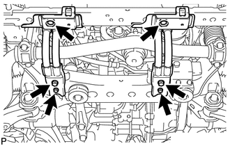
7. REMOVE FRONT SUSPENSION MEMBER BRACE SUB-ASSEMBLY
|
(a) Remove the 6 bolts and 2 member braces from the front frame assembly. |
|
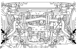
8. REMOVE FRONT STABILIZER END BRACKET
|
(a) Remove the 4 bolts and 2 brackets from the lower arm. |
|
9. REMOVE FRONT STABILIZER BAR
|
(a) Remove the 4 bolts, 2 front stabilizer lower brackets and front stabilizer bar. |
|
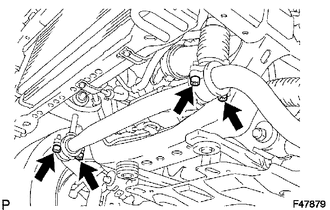
(b) Remove the 2 front stabilizer link bushes and front stabilizer lower bracket bushes from the front stabilizer bar.
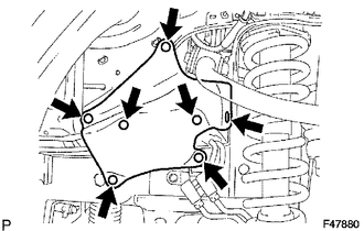
10. REMOVE FRONT FENDER APRON SEAL LH
|
(a) Remove the 7 clips and front apron seal LH. |
|
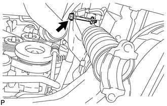
11. REMOVE FRAME APRON SEAL BRACKET
|
(a) Remove the bolt and bracket. |
|
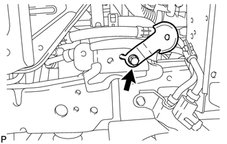
12. DISCONNECT NO. 1 FRONT STABILIZER CONTROL TUBE ASSEMBLY
|
(a) Using a union nut wrench, disconnect the 2 front stabilizer control tubes. |
|
(b) Remove the bolt.
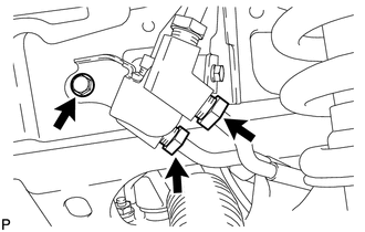
13. REMOVE FRONT STABILIZER WITH TUBE CYLINDER ASSEMBLY
(a) Remove the bolt, nut and front stabilizer with tube cylinder assembly.
NOTICE:
- Turn the bolt while holding the nut.
- Do not loosen or remove the flare nuts labeled A and B in the illustration.
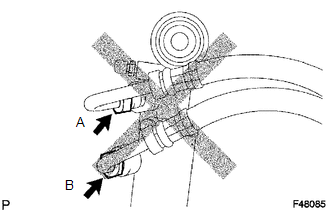
- Do not hold the front stabilizer with tube cylinder assembly by the cylinder boot.
(b) Remove the 2 bleeder plug caps and bleeder plugs from the front stabilizer with tube cylinder assembly.
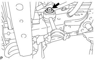
14. REMOVE FRONT STABILIZER LINK ASSEMBLY RH
|
(a) Remove the bolt and front stabilizer link assembly. |
|
 Components
COMPONENTS
ILLUSTRATION
ILLUSTRATION
ILLUSTRATION
...
 Installation
INSTALLATION
PROCEDURE
1. TEMPORARILY INSTALL FRONT STABILIZER LINK ASSEMBLY RH
(a) Temporarily install the front stabilizer link assembly with the bolt.
HINT:
Make sure that the i ...
Other materials about Toyota 4Runner:
Data List / Active Test
DATA LIST / ACTIVE TEST
1. DATA LIST
NOTICE:
In the table below, the values listed under "Normal Condition" are reference
values. Do not depend solely on these reference values when deciding whether a part
is faulty or not.
HINT:
Using the T ...
Removal
REMOVAL
PROCEDURE
1. DISCONNECT CABLE FROM NEGATIVE BATTERY TERMINAL
NOTICE:
When disconnecting the cable, some systems need to be initialized after the cable
is reconnected (See page ).
2. REMOVE NO. 2 DOOR INSIDE HANDLE BEZEL LH
3. REMOVE REAR DO ...

0.0068