Toyota 4Runner: Removal
REMOVAL
CAUTION / NOTICE / HINT
HINT:
- Use the same procedure for the RH and LH sides.
- The procedure listed below is for the LH side.
PROCEDURE
1. REMOVE REAR NO. 2 SEAT ASSEMBLY
(a) Remove the rear No. 2 seat assembly (See page
.gif) ).
).
2. REMOVE REAR NO. 1 FLOOR STEP COVER
3. REMOVE QUARTER SCUFF PLATE LH
4. REMOVE REAR DOOR SCUFF PLATE LH
5. REMOVE REAR DOOR OPENING TRIM WEATHERSTRIP LH
6. REMOVE REAR NO. 1 SEAT OUTER LAP BELT ANCHOR COVER
7. REMOVE NO. 1 LUGGAGE COMPARTMENT TRIM HOOK
8. REMOVE FRONT DECK SIDE TRIM COVER LH
9. REMOVE DECK TRIM SIDE PANEL ASSEMBLY LH
|
(a) Remove the bolt and disconnect the rear No. 1 seat outer belt floor anchor. |
|
.png)
|
(b) Remove the bolt and disconnect the rear No. 2 seat outer belt floor anchor. |
|
.png)
|
(c) for RH Side: Remove the bolt and disconnect the rear No. 2 seat outer belt floor anchor. |
|
.png)
(d) Remove the 3 bolts and 2 screws.
(e) Detach the 7 clips, 5 claws and 2 guides and remove the deck trim side panel.
.png)
10. REMOVE REAR NO. 2 WINDOW SIDE GARNISH ASSEMBLY LH
11. REMOVE REAR WINDOW SIDE GARNISH ASSEMBLY LH
12. REMOVE REAR NO. 2 SEAT OUTER BELT ASSEMBLY LH
|
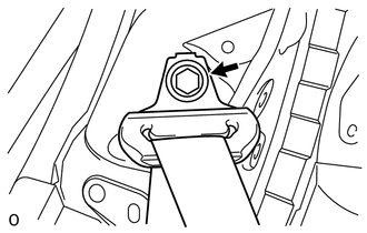
(a) Remove the bolt and rear No. 2 seat outer belt shoulder anchor. |
|
|
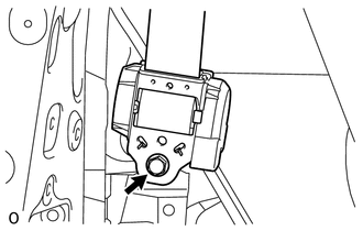
(b) Remove the 2 bolts and rear No. 2 seat outer belt assembly. |
|
13. REMOVE REAR SEAT OUTER BELT ANCHOR PLATE SUB-ASSEMBLY LH
|
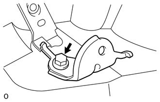
(a) Remove the bolt and anchor plate. |
|
14. REMOVE SEAT BELT ANCHOR PLATE ASSEMBLY
|
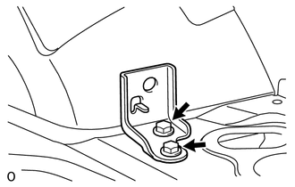
(a) Remove the 2 bolts and anchor plate. |
|
 Components
COMPONENTS
ILLUSTRATION
ILLUSTRATION
ILLUSTRATION
...
 Inspection
INSPECTION
PROCEDURE
1. INSPECT REAR NO. 1 SEAT OUTER BELT ASSEMBLY
(a) Check the ELR.
(1) When the inclination of the retractor is 15° or less, check that
the belt can be pulled ...
Other materials about Toyota 4Runner:
Removal
REMOVAL
PROCEDURE
1. DISCONNECT CABLE FROM NEGATIVE BATTERY TERMINAL
CAUTION:
Wait at least 90 seconds after disconnecting the cable from the negative (-)
battery terminal to disable the SRS system.
NOTICE:
When disconnecting the cable, some systems ne ...
Window Defogger Wire
On-vehicle Inspection
ON-VEHICLE INSPECTION
PROCEDURE
1. INSPECT BACK WINDOW GLASS (DEFOGGER WIRE)
NOTICE:
When cleaning the glass, wipe the glass along the wire using a soft,
dry cloth. Take care not to damage the defogger wires.
Do not ...

0.0066