Toyota 4Runner: Short in Telephone Antenna Circuit (B1573,B15CB)
DESCRIPTION
This DTC is stored when the DCM (Telematics Transceiver) detects an open or a short in the telephone and GPS antenna circuit. The DCM (Telematics Transceiver) sends and receives signals at a radio frequency of between 824 and 894 MHz or 1850 and 1990 MHz through the telephone and GPS antenna.
|
DTC Code |
DTC Detection Condition |
Trouble Area |
|---|---|---|
|
B1573 |
The telephone and GPS antenna impedance is lower than the malfunction criterion for 10 seconds when the ignition switch is ON. |
|
|
B15CB |
The telephone and GPS antenna impedance is lower than the malfunction criterion for 10 seconds when the ignition switch is ON. |
HINT:
Refer to "Parts Location" for the installation location of the telephone and
GPS antenna cord (See page .gif) ).
).
PROCEDURE
|
1. |
CHECK FOR DTC |
(a) Turn the ignition switch off.
(b) Connect the Techstream to the DLC3.
(c) Turn the ignition switch to ON and wait for 10 seconds.
(d) Perform "Health Check" and check for current DTCs (See page
).
Result
|
Result |
Proceed to |
|---|---|
|
DTC B1573 or B15CB is output |
A |
|
DTC B1573 and B15CB is not output |
B |
| B | .gif) |
CHECK FOR INTERMITTENT PROBLEMS |
|
.gif)
|
2. |
INSPECT TELEPHONE AND GPS ANTENNA (DCM - TELEPHONE AND GPS ANTENNA) |
|
(a) Disconnect the telephone and GPS antenna connector. |
|
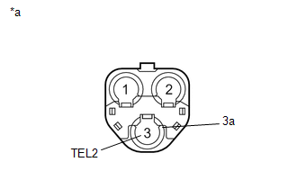
(b) Measure the resistance according to the value(s) in the table below.
Standard Resistance:
|
Tester Connection |
Condition |
Specified Condition |
|---|---|---|
|
3 (TEL2) - 3a |
Always |
4 to 11 kΩ |
|
*a |
Telephone and GPS Antenna Assembly |
| NG | |
REPLACE TELEPHONE AND GPS ANTENNA (TELEPHONE ANTENNA ASSEMBLY) |
|
|
3. |
INSPECT TELEPHONE AND GPS ANTENNA CORD (NO. 3 ANTENNA CORD SUB-ASSEMBLY) |
|
(a) Disconnect the No. 3 antenna cord sub-assembly from the telephone and GPS antenna assembly connector. |
|
(b) Disconnect the No. 3 antenna cord sub-assembly from the No. 2 antenna cord sub-assembly.
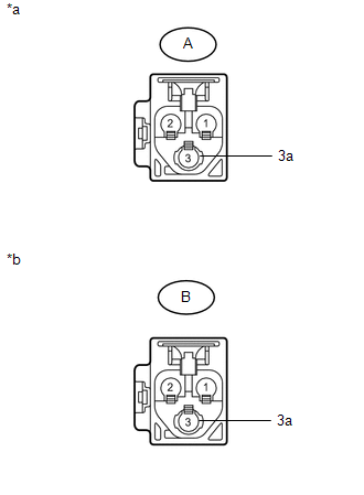
(c) Measure the resistance according to the value(s) in the table below.
Standard Resistance:
|
Tester Connection |
Condition |
Specified Condition |
|---|---|---|
|
A-3 - B-3 |
Always |
Below 1 Ω |
|
A-3a - B-3a |
Always |
Below 1 Ω |
|
A-3 - Body ground |
Always |
10 kΩ or higher |
|
A-3a - Body ground |
Always |
10 kΩ or higher |
|
*a |
Telephone and GPS Antenna Assembly Side |
|
*b |
No. 2 Antenna Cord Sub-assembly Side |
| NG | |
REPLACE TELEPHONE AND GPS ANTENNA CORD (NO. 3 ANTENNA CORD SUB-ASSEMBLY) |
|
|
4. |
INSPECT TELEPHONE AND GPS ANTENNA CORD (NO. 2 ANTENNA CORD SUB-ASSEMBLY) |
|
(a) Disconnect the No. 2 antenna cord sub-assembly from the No. 3 antenna cord sub-assembly. |
|
(b) Disconnect the No. 2 antenna cord sub-assembly from the No. 2 instrument panel wire.
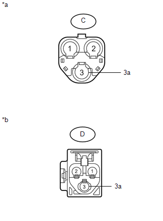
(c) Measure the resistance according to the value(s) in the table below.
Standard Resistance:
|
Tester Connection |
Condition |
Specified Condition |
|---|---|---|
|
C-3 - D-3 |
Always |
Below 1 Ω |
|
C-3a - D-3a |
Always |
Below 1 Ω |
|
C-3 - Body ground |
Always |
10 kΩ or higher |
|
C-3a - Body ground |
Always |
10 kΩ or higher |
|
*a |
Telephone Antenna Cord Sub-assembly Side |
|
*b |
No. 2 Instrument Panel Wire |
| NG | |
REPLACE TELEPHONE AND GPS ANTENNA CORD (NO. 2 ANTENNA CORD SUB-ASSEMBLY) |
|
|
5. |
INSPECT TELEPHONE AND GPS ANTENNA CORD (NO. 2 INSTRUMENT PANEL WIRE) |
|
(a) Disconnect the No. 2 instrument panel wire from the No. 2 antenna cord sub-assembly. |
|
(b) Disconnect the No. 2 instrument panel wire from the DCM (telematics transceiver).
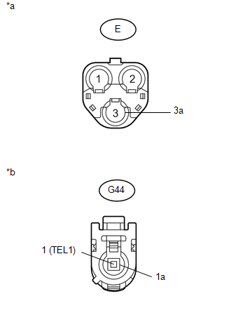
(c) Measure the resistance according to the value(s) in the table below.
Standard Resistance:
|
Tester Connection |
Condition |
Specified Condition |
|---|---|---|
|
E-3 - G44-1 (TEL1) |
Always |
Below 1 Ω |
|
E-3a - G44-1a |
Always |
Below 1 Ω |
|
E-3 - Body ground |
Always |
10 kΩ or higher |
|
E-3a - Body ground |
Always |
10 kΩ or higher |
|
*a |
No. 2 Antenna Cord Sub-assembly Side |
|
*b |
DCM (Telematics Transceiver) Side |
| NG | |
REPLACE TELEPHONE AND GPS ANTENNA CORD (NO. 2 INSTRUMENT PANEL WIRE) |
|
|
6. |
REPLACE TELEPHONE AND GPS ANTENNA (TELEPHONE ANTENNA ASSEMBLY) |
(a) Replace the telephone and GPS antenna with a normally functioning one and
check if the same problem occurs again (See page
).
OK:
The system returns to normal.
| OK | |
END (TELEPHONE AND GPS ANTENNA IS DEFECTIVE) |
|
|
7. |
REPLACE DCM (TELEMATICS TRANSCEIVER) |
(a) Replace the DCM (Telematics Transceiver) (See page
).
NOTICE:
- The ignition switch must be off.
- Do not replace the DCM (Telematics Transceiver) with one from another vehicle.
| NEXT | |
PERFORM DCM ACTIVATION |
 Telephone Microphone Error (B1572)
DESCRIPTION
This DTC is stored when the DCM (Telematics Transceiver) detects a malfunction
in the telephone microphone assembly circuit.
DTC Code
DTC Detection Condition
...
 GPS Signal Unreceived (B1583)
DESCRIPTION
If GPS satellite signals cannot be acquired for 24 consecutive kilometers (15
consecutive miles), this DTC is set.
DTC Code
DTC Detection Condition
Tro ...
Other materials about Toyota 4Runner:
Rear Power Window RH does not Operate with Rear Power Window Switch RH
DESCRIPTION
If the manual up/down function does not operate, there may be a malfunction
in the rear power window regulator switch, rear power window regulator motor,
harness or connector.
WIRING DIAGRAM
CAUTION / NOTICE / HINT
NOTICE ...
Reverse Signal Circuit
DESCRIPTION
The radio and display receiver assembly receives a reverse signal from the park/neutral
position switch assembly.
WIRING DIAGRAM
PROCEDURE
1.
CHECK HARNESS AND CONNECTOR (REVERSE SIGNAL)
(a) Disconnect the G ...

0.0281