Toyota 4Runner: Suspension Control System(w/ Reas)
Precaution
PRECAUTION
1. HANDLING PRECAUTIONS FOR CENTER UNIT AND SHOCK ABSORBER
(a) Replacement of each unit is allowed if there is no fluid leakage. However, in the case of fluid leakage from the system, replace both the absorber and center unit as a set.
(b) It is possible to replace a unit only if it is the first time the part is being replaced. Replace the system parts as a set if it is the second time or later.
(c) When carrying each unit, be sure to hold the body of the unit. Never hold the body by the joint parts or hoses.
Also, do not deform metal tubes.
(d) The units should not be at a high temperature at the time of replacement.
(e) As the shock absorber could be damaged by sudden temperature changes after it is disconnected from the center unit, be careful when storing it.
(f) Do not loosen the union bolt except when disposing of a unit.
(g) Never loosen the absorber hoses or the flare nuts at the joint parts.
2. REMOVAL AND INSTALLATION PRECAUTIONS FOR CENTER UNIT AND SHOCK ABSORBER
(a) Conduct the operations with the shock absorbers extended by jacking up the vehicle.
(b) Never apply a large compressive load to the shock absorbers, such as that applied when the tires contact the ground, before connecting the shock absorbers to the center unit to avoid damaging them.
(c) Do not allow any foreign matter to contact the joint surfaces of the parts. If any foreign matter adheres to a part, wipe it away to avoid damage to the O-rings.
(d) Be sure to insert the claws of the brackets on the front absorber hose side, rear absorber hose side and middle unit joint part into the holes in the frame.
(e) Never loosen the absorber hoses or the flare nuts at the joint parts.
(f) For the joint that connects supplied parts, tighten the joint while checking the gap spacing shown in the illustration.
.png)
Torque:
25 N·m {255 kgf·cm, 18 ft·lbf}
Standard clearance:
1 mm (0.0394 in.)
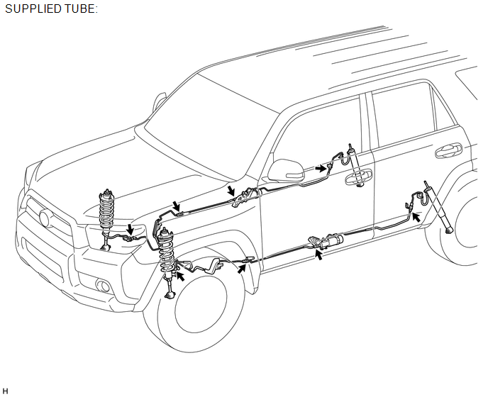
3. SERVICE PARTS FOR NO. 1 CENTER CONTROL ABSORBER TUBE
(a) The No. 1 center control absorber tubes are divided into 2 parts (front and rear) when supplied as replacement parts.
On-vehicle Inspection
ON-VEHICLE INSPECTION
PROCEDURE
1. CHECK FLUID LEAKAGE
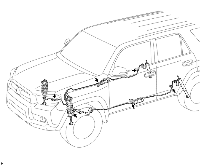
(a) Check the tube connections and parts shown in the illustration for fluid leakage.


 Bleeding
BLEEDING
PROCEDURE
1. BLEED AIR FROM SUSPENSION FLUID
CAUTION:
Be sure to check the pipe connections and whether or not any hydraulic
circuit parts are damaged before performing work a ...
 Tire / Wheel
...
Other materials about Toyota 4Runner:
Vehicle Control History
VEHICLE CONTROL HISTORY
1. Function Overview
(a) The vehicle control history is a function that records control data (record
data) when triggered by specific vehicle behavior. When DTCs are not detected according
to information provided by customers, by ...
Installation
INSTALLATION
PROCEDURE
1. INSTALL POWER WINDOW REGULATOR MOTOR ASSEMBLY LH
NOTICE:
The regulator arm must be below the intermediate position when installing the
rear power window regulator motor assembly.
(a) Using a T25 "TORX" sock ...
0.0135
