Toyota 4Runner: System Diagram
Toyota 4Runner Service Manual / Audio / Visual / Telematics / Navigation / Multi Info Display / Navigation System / System Diagram
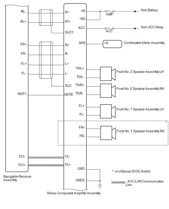
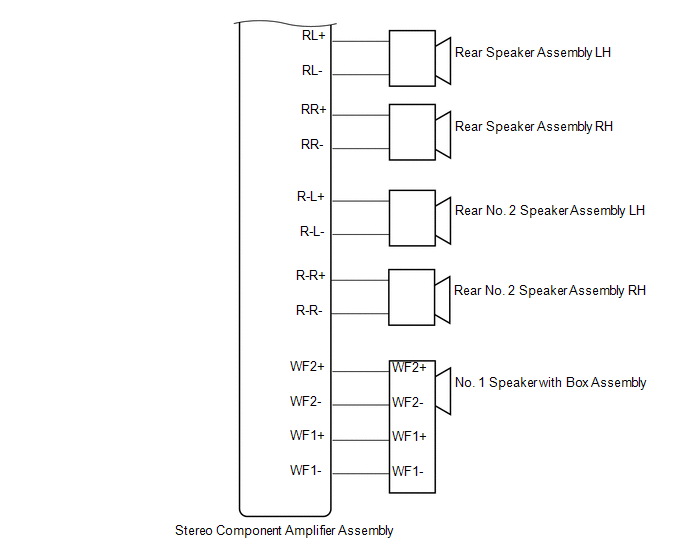
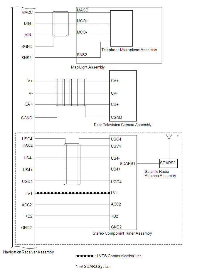
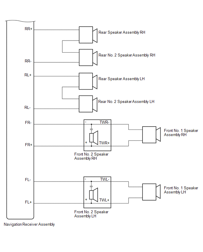
SYSTEM DIAGRAM
1. for 9 speakers:
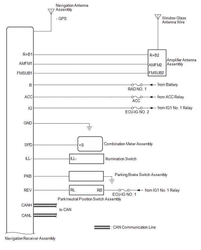
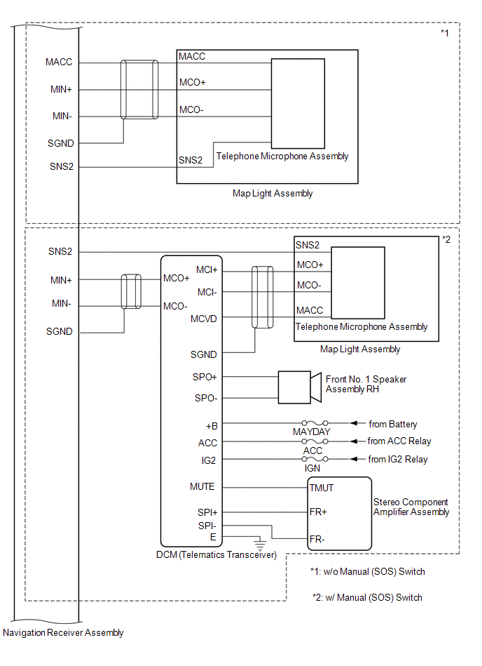
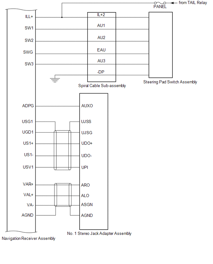
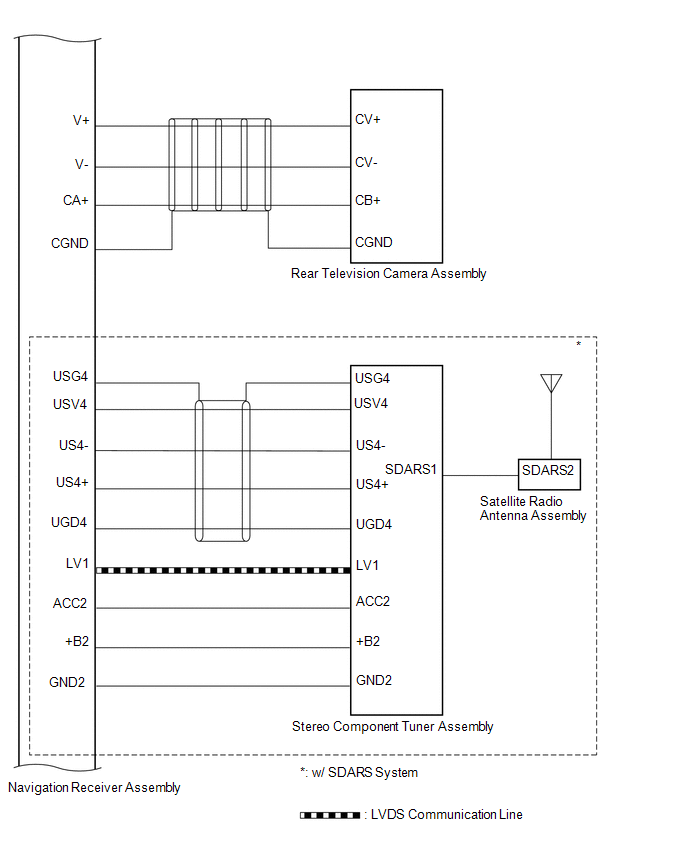
2. for 8 speakers:
 System Description
SYSTEM DESCRIPTION
1. NAVIGATION SYSTEM OUTLINE
(a) Vehicle position tracking methods
It is essential that the navigation system correctly tracks the current vehicle
position and displays it on t ...
 How To Proceed With Troubleshooting
CAUTION / NOTICE / HINT
HINT:
Use the following procedure to troubleshoot the navigation system.
*: Use the Techstream.
PROCEDURE
1.
VEHICLE BROUGHT TO ...
Other materials about Toyota 4Runner:
How To Proceed With Troubleshooting
CAUTION / NOTICE / HINT
HINT:
Use these procedures to troubleshoot the air conditioning system.
*: Use the Techstream.
PROCEDURE
1.
VEHICLE BROUGHT TO WORKSHOP
NEXT
...
Disassembly
DISASSEMBLY
PROCEDURE
1. INSPECT DIFFERENTIAL RING GEAR BACKLASH
(a) Using SST and a dial indicator, measure the ring gear backlash.
SST: 09564-32011
Standard backlash:
0.11 to 0.21 mm (0.00433 to 0.00827 in.)
If the backlash is not as specified, adj ...
© 2016-2026 | www.to4runner.net

0.0082
0.0082