Toyota 4Runner: System Diagram
SYSTEM DIAGRAM
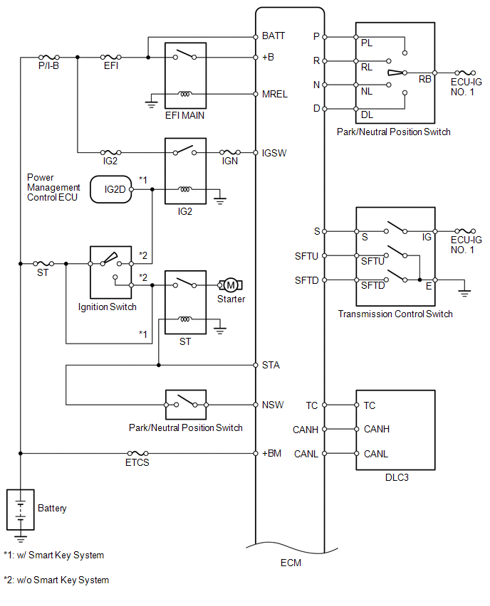
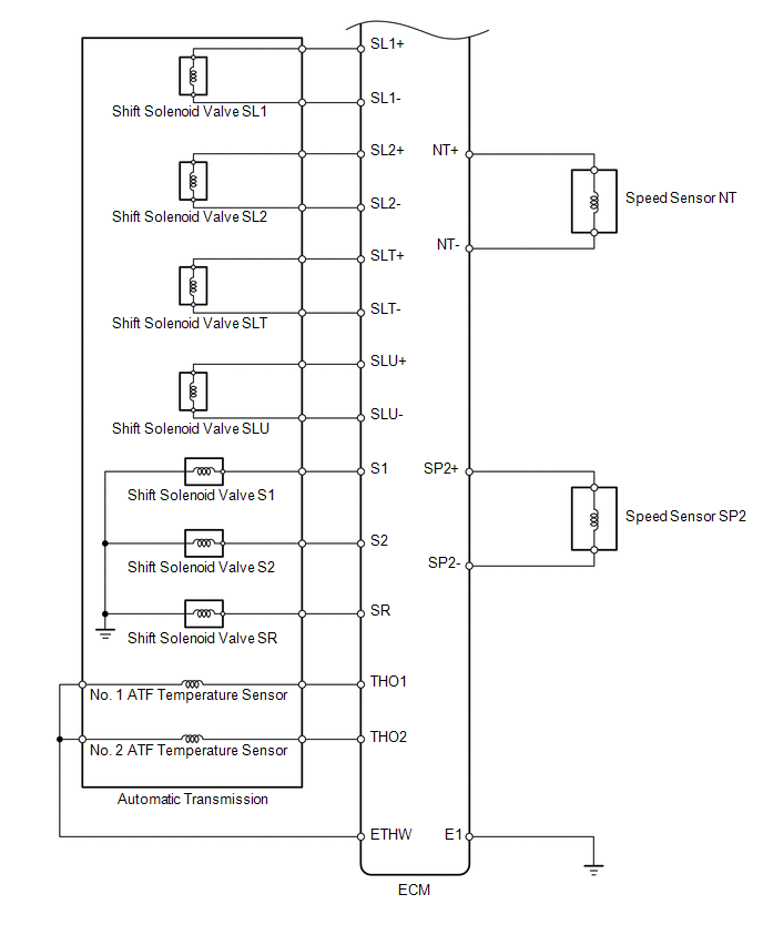
The configuration of the electronic control system for the A750E automatic transmission is as shown in the following chart.
 Parts Location
PARTS LOCATION
ILLUSTRATION
ILLUSTRATION
...
 System Description
SYSTEM DESCRIPTION
1. SYSTEM DESCRIPTION
(a) The Electronic Controlled Automatic Transmission (ECT) is an automatic transmission
that electronically controls shift timing using the Engine Control ...
Other materials about Toyota 4Runner:
Installation
INSTALLATION
PROCEDURE
1. INSTALL WINDSHIELD WASHER MOTOR AND PUMP ASSEMBLY
(a) Install the windshield washer motor and pump assembly to the packing of the
washer jar.
2. INSTALL WASHER JAR
(a) Attach the guide to install the washer jar, and ...
Open in Outside Luggage Compartment Electrical Key Antenna Circuit (B27A8)
DESCRIPTION
The certification ECU generates a request signal and transmits the signal to
the electrical key antenna (outside luggage). The electrical key antenna (outside
luggage) detects that the electrical key is brought close to the vehicle, and when
...

0.0066