Toyota 4Runner: Terminals Of Ecu
TERMINALS OF ECU
1. CHECK DRIVER SIDE JUNCTION BLOCK ASSEMBLY AND MAIN BODY ECU (MULTIPLEX NETWORK BODY ECU)
.png)
(a) Remove the main body ECU (multiplex network body ECU) (See page
.gif) ).
).
(b) Measure the voltage and resistance according to the value(s) in the table below.
|
Terminal No. (Symbol) |
Wiring Color |
Terminal Description |
Condition |
Specified Condition |
|---|---|---|---|---|
|
A-30 (BECU) - Body ground |
- |
Battery power supply |
Always |
11 to 14 V |
|
A-31 (ALTB) - Body ground |
- |
Battery power supply |
Always |
11 to 14 V |
|
A-32 (IG) - Body ground |
- |
Ignition switch power supply |
Ignition switch ON |
11 to 14 V |
|
A-32 (IG) - Body ground |
- |
Ignition switch power supply |
Ignition switch off |
Below 1 V |
|
A-29 (ACC) - Body ground |
- |
ACC power supply |
Ignition switch ACC |
11 to 14 V |
|
A-29 (ACC) - Body ground |
- |
ACC power supply |
Ignition switch off |
Below 1 V |
|
A-11 (GND1) - Body ground |
- |
Ground |
Always |
Below 1 Ω |
|
F10-3 (GND2) - Body ground |
W-B - Body ground |
Ground |
Always |
Below 1 Ω |
If the result is not as specified, there may be a malfunction in the wire harness.
(c) Install the main body ECU (multiplex network body ECU).
(d) Measure the voltage according to the value(s) in the table below.
|
Terminal No. (Symbol) |
Wiring Color |
Terminal Description |
Condition |
Specified Condition |
|---|---|---|---|---|
|
2F-27 (FLCY) - Body ground |
R - Body ground |
Front door LH courtesy light switch input |
Front door LH open |
Below 1 V |
|
2F-27 (FLCY) - Body ground |
R - Body ground |
Front door LH courtesy light switch input |
Front door LH closed |
11 to 14 V |
|
2B-15 (FRCY) - Body ground |
B - Body ground |
Front door RH courtesy light switch input |
Front door RH open |
Below 1 V |
|
2B-15 (FRCY) - Body ground |
B - Body ground |
Front door RH courtesy light switch input |
Front door RH closed |
11 to 14 V |
|
F8-3 (LCTY) - Body ground |
V - Body ground |
Rear door LH courtesy light switch input |
Rear door LH open |
Below 1 V |
|
F8-3 (LCTY) - Body ground |
V - Body ground |
Rear door LH courtesy light switch input |
Rear door LH closed |
11 to 14 V |
|
F10-27 (RCTY) - Body ground |
R - Body ground |
Rear door RH courtesy light switch input |
Rear door RH open |
Below 1 V |
|
F10-27 (RCTY) - Body ground |
R - Body ground |
Rear door RH courtesy light switch input |
Rear door RH closed |
11 to 14 V |
|
F9-9 (L1) - Body ground |
B - Body ground |
Door control switch lock input |
Door control switch on |
Below 1 V |
|
F9-9 (L1) - Body ground |
B - Body ground |
Door control switch lock input |
Door control switch off |
Pulse generation (See waveform 1 or 2) |
|
F9-10 (UL1) - Body ground |
W - Body ground |
Door control switch unlock input |
Door control switch on |
Below 1 V |
|
F9-10 (UL1) - Body ground |
W - Body ground |
Door control switch unlock input |
Door control switch off |
Pulse generation (See waveform 3 or 4) |
|
F9-11 (L2) - Body ground |
LG - Body ground |
Driver side door key-linked lock input |
Driver side door key cylinder in lock position |
Below 1 V |
|
F9-11 (L2) - Body ground |
LG - Body ground |
Driver side door key-linked lock input |
Ignition switch off, all doors closed and driver side door key cylinder in neutral position |
Pulse generation (See waveform 5 or 6) |
|
F9-24 (UL3) - Body ground |
GR - Body ground |
Driver side door key-linked unlock input |
Driver side door key cylinder in unlock position |
Below 1 V |
|
F9-24 (UL3) - Body ground |
GR - Body ground |
Driver side door key-linked unlock input |
Ignition switch off, all doors closed and driver side door key cylinder in neutral position |
Pulse generation (See waveform 7 or 8) |
|
2B-3 (ACT+) - Body ground |
L - Body ground |
Door lock motor lock drive output (except rear LH and back door) |
Driver or passenger side door control switch not pushed and driver side door key cylinder in neutral position |
Below 1 V |
|
2B-3 (ACT+) - Body ground |
L - Body ground |
Door lock motor lock drive output (except rear LH and back door) |
Lock side of driver or passenger side door control switch pushed, or driver side door key cylinder in lock position |
11 to 14 V |
|
2F-8 (ACT+) - Body ground |
L - Body ground |
Door lock motor lock drive output (for rear LH) |
Driver or passenger side door control switch not pushed and driver side door key cylinder in neutral position |
Below 1 V |
|
2F-8 (ACT+) - Body ground |
L - Body ground |
Door lock motor lock drive output (for rear LH) |
Lock side of driver or passenger side door control switch pushed, or driver side door key cylinder in lock position |
11 to 14 V |
|
2B-1 (ACTD) - Body ground |
W - Body ground |
Driver side door lock motor unlock drive output |
Driver or passenger side door control switch not pushed and driver side door key cylinder in neutral position |
Below 1 V |
|
2B-1 (ACTD) - Body ground |
W - Body ground |
Driver side door lock motor unlock drive output |
Unlock side of driver or passenger side door control switch pushed, or driver side door key cylinder in unlock position |
11 to 14 V |
|
2B-2 (ACT-) - Body ground |
W - Body ground |
Door lock motor unlock drive output (for front RH and rear RH) |
Driver or passenger side door control switch not pushed and driver side door key cylinder in neutral position |
Below 1 V |
|
2B-2 (ACT-) - Body ground |
W - Body ground |
Door lock motor unlock drive output (for front RH and rear RH) |
Unlock side of driver or passenger side door control switch pushed, or driver side door key cylinder in unlock position |
11 to 14 V |
|
2F-10 (ACT-) - Body ground |
W - Body ground |
Door lock motor unlock drive output (for rear LH) |
Driver or passenger side door control switch not pushed and driver side door key cylinder in neutral position |
Below 1 V |
|
2F-10 (ACT-) - Body ground |
W - Body ground |
Door lock motor unlock drive output (for rear LH) |
Unlock side of driver or passenger side door control switch pushed, or driver side door key cylinder in unlock position |
11 to 14 V |
|
2F-9 (TR+) - Body ground |
R - Body ground |
Back door unlock motor output |
Back door opener switch pushed |
Below 1 V |
|
2F-9 (TR+) - Body ground |
R - Body ground |
Back door unlock motor output |
Back door opener switch free |
11 to 14 V |
|
F9-7 (LSFL) - Body ground |
G - Body ground |
Front door LH lock position switch input |
Front door LH unlocked |
Below 1 V |
|
F9-7 (LSFL) - Body ground |
G - Body ground |
Front door LH lock position switch input |
Ignition switch off, all doors closed and front door LH locked |
Pulse generation (See waveform 9 or 10) |
|
F9-18 (LSFR) - Body ground |
G - Body ground |
Front door RH lock position switch input |
Front door RH unlocked |
Below 1 V |
|
F9-18 (LSFR) - Body ground |
G - Body ground |
Front door RH lock position switch input |
Ignition switch off, all doors closed and front door RH locked |
Pulse generation (See waveform 11 or 12) |
|
2F-25 (LSWL) - Body ground |
V - Body ground |
Rear door LH lock position switch input |
Rear door LH unlocked |
Below 1 V |
|
2F-25 (LSWL) - Body ground |
V - Body ground |
Rear door LH lock position switch input |
Ignition switch off, all doors closed and rear door LH locked |
Pulse generation (See waveform 13 or 14) |
|
F10-2 (LSWR) - Body ground |
V - Body ground |
Rear door RH lock position switch input |
Rear door RH unlocked |
Below 1 V |
|
F10-2 (LSWR) - Body ground |
V - Body ground |
Rear door RH lock position switch input |
Ignition switch off, all doors closed and rear door RH locked |
Pulse generation (See waveform 15 or 16) |
If the result is not as specified, the main body ECU (multiplex network body ECU) or driver side junction block assembly may have a malfunction.
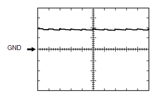
(e) Using an oscilloscope, check waveform 1
.png) Waveform 1 (Reference)
Waveform 1 (Reference)
|
Item |
Content |
|---|---|
|
Terminal No. (Symbol) |
F9-9 (L1) - Body ground |
|
Tool Setting |
5 V/DIV., 20 ms/DIV. |
|
Condition |
Door control switch off |
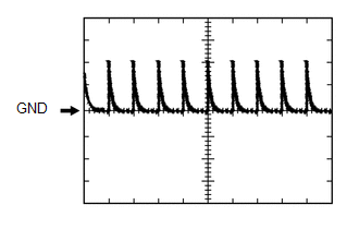
(f) Using an oscilloscope, check waveform 2.
 Waveform 2 (Reference)
|
Item |
Content |
|---|---|
|
Terminal No. (Symbol) |
F9-9 (L1) - Body ground |
|
Tool Setting |
5 V/DIV., 20 ms/DIV. |
|
Condition |
Door control switch off |
(g) Using an oscilloscope, check waveform 3.
.png) Waveform 3 (Reference)
Waveform 3 (Reference)
|
Item |
Content |
|---|---|
|
Terminal No. (Symbol) |
F9-10 (UL1) - Body ground |
|
Tool Setting |
5 V/DIV., 20 ms/DIV. |
|
Condition |
Door control switch off |
(h) Using an oscilloscope, check waveform 4.
 Waveform 4 (Reference)
|
Item |
Content |
|---|---|
|
Terminal No. (Symbol) |
F9-10 (UL1) - Body ground |
|
Tool Setting |
5 V/DIV., 20 ms/DIV. |
|
Condition |
Door control switch off |
(i) Using an oscilloscope, check waveform 5.
Waveform 5 (Reference)
|
Item |
Content |
|---|---|
|
Terminal No. (Symbol) |
F9-11 (L2) - Body ground |
|
Tool Setting |
5 V/DIV., 20 ms/DIV. |
|
Condition |
Ignition switch off, all doors closed and front door key cylinder in neutral position |
(j) Using an oscilloscope, check waveform 6.
Waveform 6 (Reference)
|
Item |
Content |
|---|---|
|
Terminal No. (Symbol) |
F9-11 (L2) - Body ground |
|
Tool Setting |
5 V/DIV., 20 ms/DIV. |
|
Condition |
Ignition switch off, all doors closed and front door key cylinder in neutral position |
(k) Using an oscilloscope, check waveform 7.
Waveform 7 (Reference)
|
Item |
Content |
|---|---|
|
Terminal No. (Symbol) |
F9-24 (UL3) - Body ground |
|
Tool Setting |
5 V/DIV., 20 ms/DIV. |
|
Condition |
Ignition switch off, all doors closed and driver side door key cylinder in neutral position |
(l) Using an oscilloscope, check waveform 8.
Waveform 8 (Reference)
|
Item |
Content |
|---|---|
|
Terminal No. (Symbol) |
F9-24 (UL3) - Body ground |
|
Tool Setting |
5 V/DIV., 20 ms/DIV. |
|
Condition |
Ignition switch off, all doors closed and driver side door key cylinder in neutral position |
(m) Using an oscilloscope, check waveform 9.
Waveform 9 (Reference)
|
Item |
Content |
|---|---|
|
Terminal No. (Symbol) |
F9-7 (LSFL) - Body ground |
|
Tool Setting |
5 V/DIV., 20 ms/DIV. |
|
Condition |
Ignition switch off, all doors closed and front door LH locked |
(n) Using an oscilloscope, check waveform 10.
Waveform 10 (Reference)
|
Item |
Content |
|---|---|
|
Terminal No. (Symbol) |
F9-7 (LSFL) - Body ground |
|
Tool Setting |
5 V/DIV., 20 ms/DIV. |
|
Condition |
Ignition switch off, all doors closed and front door LH locked |
(o) Using an oscilloscope, check waveform 11.
Waveform 11 (Reference)
|
Item |
Content |
|---|---|
|
Terminal No. (Symbol) |
F9-18 (LSFR) - Body ground |
|
Tool Setting |
5 V/DIV., 20 ms/DIV. |
|
Condition |
Ignition switch off, all doors closed and front door RH locked |
(p) Using an oscilloscope, check waveform 12.
Waveform 12 (Reference)
|
Item |
Content |
|---|---|
|
Terminal No. (Symbol) |
F9-18 (LSFR) - Body ground |
|
Tool Setting |
5 V/DIV., 20 ms/DIV. |
|
Condition |
Ignition switch off, all doors closed and front door RH locked |
(q) Using an oscilloscope, check waveform 13.
Waveform 13 (Reference)
|
Item |
Content |
|---|---|
|
Terminal No. (Symbol) |
2F-25 (LSWL) - Body ground |
|
Tool Setting |
5 V/DIV., 20 ms/DIV. |
|
Condition |
Ignition switch off, all doors closed and rear door LH locked |
(r) Using an oscilloscope, check waveform 14.
Waveform 14 (Reference)
|
Item |
Content |
|---|---|
|
Terminal No. (Symbol) |
2F-25 (LSWL) - Body ground |
|
Tool Setting |
5 V/DIV., 20 ms/DIV. |
|
Condition |
Ignition switch off, all doors closed and rear door LH locked |
(s) Using an oscilloscope, check waveform 15.
Waveform 15 (Reference)
|
Item |
Content |
|---|---|
|
Terminal No. (Symbol) |
F10-2 (LSWR) - Body ground |
|
Tool Setting |
5 V/DIV., 20 ms/DIV. |
|
Condition |
Ignition switch off, all doors closed and rear door RH locked |
(t) Using an oscilloscope, check waveform 16.
Waveform 16 (Reference)
|
Item |
Content |
|---|---|
|
Terminal No. (Symbol) |
F10-2 (LSWR) - Body ground |
|
Tool Setting |
5 V/DIV., 20 ms/DIV. |
|
Condition |
Ignition switch off, all doors closed and rear door RH locked |
2. CHECK MULTIPLEX NETWORK DOOR ECU (BACK DOOR P/W)
.png)
(a) Disconnect the V2 and W10 multiplex network door ECU (back door P/W) connectors.
(b) Measure the voltage and resistance according to the value(s) in the table below.
HINT:
Measure the values on the wire harness side with the connector disconnected.
|
Terminal No. (Symbol) |
Wiring Color |
Terminal Description |
Condition |
Specified Condition |
|---|---|---|---|---|
|
V2-1 (BDR) - Body ground |
B - Body ground |
Battery power supply |
Always |
11 to 14 V |
|
V2-7 (BECU) - Body ground |
L - Body ground |
Battery power supply |
Always |
11 to 14 V |
|
V2-8 (SIG) - Body ground |
G - Body ground |
Ignition switch power supply |
Ignition switch ON |
11 to 14 V |
|
V2-8 (SIG) - Body ground |
G - Body ground |
Ignition switch power supply |
Ignition switch off |
Below 1 V |
|
V2-6 (GND) - Body ground |
W-B - Body ground |
Ground |
Always |
Below 1 Ω |
If the result is not as specified, there may be a malfunction in the wire harness.
(c) Reconnect the V2 and W10 multiplex network door ECU (back door P/W) connectors.
(d) Measure the voltage according to the value(s) in the table below.
|
Terminal No. (Symbol) |
Wiring Color |
Terminal Description |
Condition |
Specified Condition |
|---|---|---|---|---|
|
W10-10 (BDCY) - W10-18 (CTYE) |
P - G |
Back door courtesy switch input |
Back door closed |
Pulse generation (See waveform 1 or 2) |
|
W10-10 (BDCY) - W10-18 (CTYE) |
P - G |
Back door courtesy switch input |
Back door open |
Below 1 V |
|
W10-16 (BKL) - W10-8 (KEYE)* |
P - V |
Tail gate control switch lock input |
Back door lock key cylinder in neutral position |
Pulse generation (See waveform 3 or 4) |
|
W10-16 (BKL) - W10-8 (KEYE)* |
P - V |
Tail gate control switch lock input |
Back door lock key cylinder in lock position |
Below 1 V |
|
W10-15 (BKUL) - W10-8 (KEYE)* |
R - V |
Tail gate control switch unlock input |
Back door lock key cylinder in neutral position |
Pulse generation (See waveform 3 or 4) |
|
W10-15 (BKUL) - W10-8 (KEYE)* |
R - V |
Tail gate control switch unlock input |
Back door lock key cylinder in unlock position |
Below 1 V |
|
W10-24 (HSW+) - W10-7 (HSW-) |
GR - LG |
Back door opener switch input |
Back door opener switch off |
Pulse generation (See waveform 5 or 6) |
|
W10-24 (HSW+) - W10-7 (HSW-) |
GR - LG |
Back door opener switch input |
Back door opener switch on |
Below 1 V |
- *: w/o Smart key System
If the result is not as specified, the multiplex network door ECU (back door P/W) may have a malfunction.
(e) Using an oscilloscope, check waveform 1.
.png) Waveform 1 (Reference)
Waveform 1 (Reference)
|
Item |
Content |
|---|---|
|
Terminal No. (Symbol) |
W10-10 (BDCY) - W10-18 (CTYE) |
|
Tool Setting |
5 V/DIV., 10 ms/DIV. |
|
Condition |
Back door closed |
(f) Using an oscilloscope, check waveform 2.
.png) Waveform 2 (Reference)
Waveform 2 (Reference)
|
Item |
Content |
|---|---|
|
Terminal No. (Symbol) |
W10-10 (BDCY) - W10-18 (CTYE) |
|
Tool Setting |
5 V/DIV., 10 ms/DIV. |
|
Condition |
Back door closed |
(g) Using an oscilloscope, check waveform 3.
Waveform 3 (Reference)
|
Item |
Content |
|---|---|
|
Terminal No. (Symbol) |
|
|
Tool Setting |
5 V/DIV., 10 ms/DIV. |
|
Condition |
Back door lock key cylinder in neutral position |
(h) Using an oscilloscope, check waveform 4.
Waveform 4 (Reference)
|
Item |
Content |
|---|---|
|
Terminal No. (Symbol) |
|
|
Tool Setting |
5 V/DIV., 10 ms/DIV. |
|
Condition |
Back door lock key cylinder in neutral position |
(i) Using an oscilloscope, check waveform 5.
Waveform 5 (Reference)
|
Item |
Content |
|---|---|
|
Terminal No. (Symbol) |
W10-24 (HSW+) - W10-7 (HSW-) |
|
Tool Setting |
5 V/DIV., 10 ms/DIV. |
|
Condition |
Back door opener switch off |
(j) Using an oscilloscope, check waveform 6.
Waveform 6 (Reference)
|
Item |
Content |
|---|---|
|
Terminal No. (Symbol) |
W10-24 (HSW+) - W10-7 (HSW-) |
|
Tool Setting |
5 V/DIV., 10 ms/DIV. |
|
Condition |
Back door opener switch off |
3. CHECK MULTIPLEX NETWORK MASTER SWITCH ASSEMBLY (See page
)
 Problem Symptoms Table
PROBLEM SYMPTOMS TABLE
HINT:
Use the table below to help determine the cause of problem symptoms.
If multiple suspected areas are listed, the potential causes of the symptoms
are lis ...
 Dtc Check / Clear
DTC CHECK / CLEAR
1. CHECK DTC
(a) Connect the Techstream to the DLC3.
(b) Turn the ignition switch to ON.
(c) Turn the Techstream on.
(d) Enter the following menus: Body Electrical / Trouble Cod ...
Other materials about Toyota 4Runner:
Compass
The compass on the accessory meter display indicates the direction in
which the vehicle is heading.
1. “MODE/ ” button
2. “SET/ ” button
3. Direction display
Displays and directions
Calibrating the compass
The direction display deviates ...
Removal
REMOVAL
PROCEDURE
1. DISCONNECT CABLE FROM NEGATIVE BATTERY TERMINAL
CAUTION:
Wait at least 90 seconds after disconnecting the cable from the negative (-)
battery terminal to disable the SRS system.
NOTICE:
When disconnecting the cable, some systems ne ...

0.0073