Toyota 4Runner: Adjustment
ADJUSTMENT
PROCEDURE
1. CHECK BRAKE PEDAL HEIGHT
|
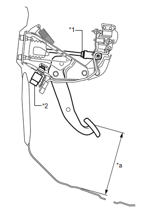
(a) Check the brake pedal height. Pedal height from Floor panel: 158.8 to 168.8 mm (6.25 to 6.46 in.) Text in Illustration
|
|
(b) Adjust the brake pedal height.
(1) Disconnect the stop light switch connector.
(2) Remove the stop light switch assembly.
(3) Loosen the push rod clevis lock nut.
(4) Adjust the brake pedal height by turning the push rod.
(5) Tighten the push rod clevis lock nut.
Torque:
26 N·m {265 kgf·cm, 19 ft·lbf}
(6) Insert the stop light switch assembly into the adjuster mounting until the switch body touches the brake pedal.
NOTICE:
Do not depress the brake pedal.
(7) Turn the stop light switch assembly a quarter turn clockwise.
Torque:
1.5 N·m {15 kgf·cm, 13 in·lbf}
or less
NOTICE:
Do not depress the pedal.
(8) Connect the connector to the stop light switch.
(9) Check the stop light switch clearance.
Stop light switch clearance:
1.5 to 2.5 mm (0.0591 to 0.0984 in.)
2. CHECK BRAKE PEDAL FREE PLAY
|
(a) Stop the engine. Depress the brake pedal several times until no vacuum is left in the brake booster. Release the brake pedal. Text in Illustration
|
|
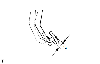
(b) Depress the pedal until a slight resistance is felt. Measure the distance as shown in the illustration.
If the pedal free play is not as specified, check the stop light switch clearance.
Pedal free play:
1.0 to 6.0 mm (0.0394 to 0.236 in.)
HINT:
Check the brake pedal free play at the same location as that used when checking the brake pedal height.
3. CHECK BRAKE PEDAL RESERVE DISTANCE
HINT:
Measure the distance from the same point as that used for the brake pedal height inspection.
(a) Release the parking brake.
|
(b) With the engine running, depress the brake pedal and measure the pedal reserve distance. Text in Illustration
Pedal reserve distance from floor panel at 490 N (50 kgf, 110.2 lbf): More than 86 mm (3.36 in.) If the distance is not as specified, troubleshoot the brake system. HINT: Insert a ruler into the slit to measure the pedal reserve distance. |
|
.png)
 Disassembly
DISASSEMBLY
PROCEDURE
1. REMOVE BRAKE PEDAL PAD
(a) Remove the brake pedal pad from the brake pedal sub-assembly.
2. REMOVE STOP LIGHT SWITCH MOUNTING ADJUSTER
(a) Remove the stop light switch mo ...
 Reassembly
REASSEMBLY
PROCEDURE
1. INSTALL STOP LIGHT SWITCH MOUNTING ADJUSTER
(a) Install a new stop light switch mounting adjuster to the brake pedal support
assembly.
2. INSTALL BRAKE PEDAL PAD
(a) Ins ...
Other materials about Toyota 4Runner:
Removal
REMOVAL
CAUTION / NOTICE / HINT
NOTICE:
When installing, coat the parts indicated by arrows with lithium soap
base glycol grease (See page ).
As high pressure is applied to the brake actuator tube No. 1, never
deform it.
Do not turn ...
AUTO LSD Indicator Light Remains ON
DESCRIPTION
During normal mode, pressing the VSC OFF switch for a short amount of time changes
vehicle to AUTO LSD mode.
WIRING DIAGRAM
CAUTION / NOTICE / HINT
NOTICE:
When replacing the master cylinder solenoid, perform calibration (See page
).
PR ...

0.0267