Toyota 4Runner: Air Conditioning Panel
Components
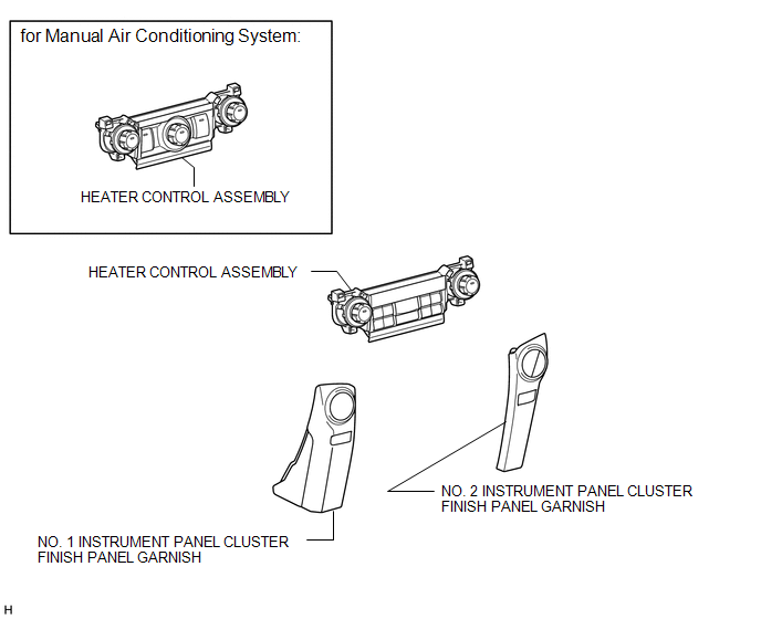
COMPONENTS
ILLUSTRATION
Installation
INSTALLATION
PROCEDURE
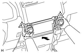
1. INSTALL HEATER CONTROL ASSEMBLY
|
(a) Attach the 4 clips to install the heater control assembly. |
|
2. INSTALL NO. 1 INSTRUMENT PANEL CLUSTER FINISH PANEL GARNISH
.gif)
3. INSTALL NO. 2 INSTRUMENT CLUSTER FINISH PANEL GARNISH
(a) Attach the 5 clips to install the No. 2 instrument cluster finish panel garnish.
Removal
REMOVAL
PROCEDURE
1. REMOVE NO. 1 INSTRUMENT PANEL CLUSTER FINISH PANEL GARNISH
.gif)
2. REMOVE NO. 2 INSTRUMENT PANEL CLUSTER FINISH PANEL GARNISH
(a) Open the instrument cluster finish panel lid.
(b) Put protective tape around the No. 2 instrument cluster finish panel garnish.
(c) Grip the No. 2 instrument cluster finish panel garnish and pull it diagonally upward toward the rear to detach the 5 clips and remove the No. 2 instrument cluster finish panel garnish.
.png) Text in Illustration
Text in Illustration
|
*1 |
Protective Tape |
- |
- |
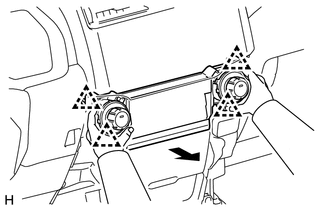
3. REMOVE HEATER CONTROL ASSEMBLY
|
(a) Detach the 4 clips and remove the heater control assembly. |
|
 Removal
REMOVAL
PROCEDURE
1. DISCONNECT CABLE FROM NEGATIVE BATTERY TERMINAL
CAUTION:
Wait at least 90 seconds after disconnecting the cable from the negative (-)
battery terminal to disable the SRS sys ...
 Air Conditioning Pressure Sensor
Components
COMPONENTS
ILLUSTRATION
On-vehicle Inspection
ON-VEHICLE INSPECTION
PROCEDURE
1. INSPECT NO. 1 PRESSURE SWITCH
(a) Connect a manifold gauge set.
...
Other materials about Toyota 4Runner:
No Response from ID BOX (B2789)
DESCRIPTION
This DTC is stored when LIN communication between the certification ECU and ID
code box stops for 10 seconds or more.
DTC Code
DTC Detection Condition
Trouble Area
B2789
No communicat ...
Problem Symptoms Table
PROBLEM SYMPTOMS TABLE
HINT:
Use the table below to help determine the cause of problem symptoms. If multiple
suspected areas are listed, the potential causes of the symptoms are listed in order
of probability in the "Suspected Area" column of ...

0.0251