Toyota 4Runner: Audio Receiver Assembly Communication Stop Mode
DESCRIPTION
|
Detection Item |
Symptom |
Trouble Area |
|---|---|---|
|
Audio Receiver Assembly Communication Stop Mode |
Either condition is met:
|
|
HINT:
For vehicles with a radio and display receiver assembly only.
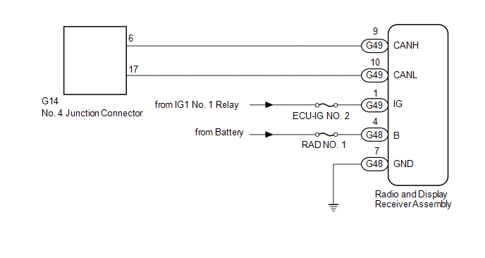
WIRING DIAGRAM
CAUTION / NOTICE / HINT
NOTICE:
Inspect the fuses for circuits related to this system before performing the following inspection procedure.
HINT:
Operating the ignition switch, any switches or any doors triggers related ECU and sensor communication with the CAN, which causes resistance variation.
PROCEDURE
|
1. |
DISCONNECT CABLE FROM NEGATIVE BATTERY TERMINAL |
(a) Disconnect the cable from the negative (-) battery terminal before measuring the resistances of the main wire and branch wire.
CAUTION:
Wait at least 90 seconds after disconnecting the cable from the negative (-) battery terminal to disable the SRS system.
NOTICE:
When disconnecting the cable, some systems need to be initialized after the cable
is reconnected (See page .gif) ).
).
|
.gif)
|
2. |
CHECK FOR OPEN IN CAN BUS WIRE (RADIO AND DISPLAY RECEIVER ASSEMBLY BRANCH WIRE) |
|
(a) Disconnect the G49 radio and display receiver assembly connector. |
|
(b) Measure the resistance according to the value(s) in the table below.
Standard Resistance:
|
Tester Connection |
Switch Condition |
Specified Condition |
|---|---|---|
|
G49-9 (CANH) - G49-10 (CANL) |
Ignition switch off |
54 to 69 Ω |
|
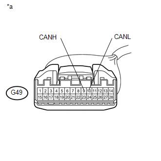
*a |
Front view of wire harness connector (to Radio and Display Receiver Assembly) |
| NG | .gif) |
REPAIR OR REPLACE RADIO AND DISPLAY RECEIVER ASSEMBLY BRANCH WIRE OR CONNECTOR (CANH, CANL) |
|
|
3. |
CHECK HARNESS AND CONNECTOR (RADIO AND DISPLAY RECEIVER ASSEMBLY - BATTERY AND BODY GROUND) |
|
(a) Connect the cable to the negative (-) battery terminal. NOTICE: When disconnecting the cable, some systems need to be initialized after
the cable is reconnected (See page |
|
(b) Disconnect the G48 and G49 radio and display receiver assembly connectors.
(c) Measure the resistance according to the value(s) in the table below.
Standard Resistance:
|
Tester Connection |
Condition |
Specified Condition |
|---|---|---|
|
G48-7 (GND) - Body ground |
Always |
Below 1 Ω |
(d) Measure the voltage according to the value(s) in the table below.
Standard Voltage:
|
Tester Connection |
Condition |
Specified Condition |
|---|---|---|
|
G49-1 (IG) - Body ground |
Ignition switch ON |
11 to 14 V |
|
G48-4 (B) - Body ground |
Always |
11 to 14 V |
|
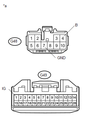
*a |
Front view of wire harness connector (to Radio and Display Receiver Assembly) |
| OK | |
REPLACE RADIO AND DISPLAY RECEIVER ASSEMBLY |
| NG | |
REPAIR OR REPLACE HARNESS OR CONNECTOR |
 Navigation Receiver Assembly Communication Stop Mode
DESCRIPTION
Detection Item
Symptom
Trouble Area
Navigation Receiver Assembly Communication Stop Mode
Either condition is met:
...
 Open in CAN Main Wire
DESCRIPTION
There may be an open circuit in the CAN main wire and/or DLC3 branch wire when
the resistance between terminals 6 (CANH) and 14 (CANL) of the DLC3 is 69 Ω or higher.
Sympto ...
Other materials about Toyota 4Runner:
Rear seats
Vehicles without third row seats
Rear seat
Pull up the seatback angle adjustment lever until the lock is released.
Vehicles with third row seats
Second row seats
1. Seat position adjustment lever
2. Seatback angle adjustment lever
Third row seats
...
Transmitter ID not Received in Main Mode (C2126/26)
DESCRIPTION
After all IDs are registered, DTC C2126/26 is stored in the tire pressure warning
ECU and the tire pressure warning light blinks for 1 minute and then comes on.
When the tire pressure warning ECU successfully receives information from all
the ...

0.0065