Toyota 4Runner: Automatic Running Board Switch
Components
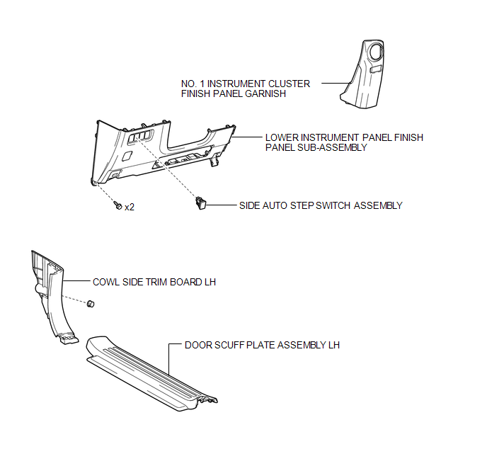
COMPONENTS
ILLUSTRATION
Removal
REMOVAL
PROCEDURE
1. REMOVE DOOR SCUFF PLATE ASSEMBLY LH
.gif)
2. REMOVE COWL SIDE TRIM BOARD LH
3. REMOVE NO. 1 INSTRUMENT CLUSTER FINISH PANEL GARNISH
4. REMOVE LOWER INSTRUMENT PANEL FINISH PANEL SUB-ASSEMBLY
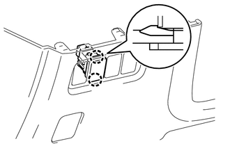
5. REMOVE SIDE AUTO STEP SWITCH ASSEMBLY
|
(a) Disengage the 2 claws and remove the side auto step switch assembly. |
|
Inspection
INSPECTION
PROCEDURE
1. INSPECT SIDE AUTO STEP SWITCH ASSEMBLY
|
(a) Measure the resistance according to the value(s) in the table below. Standard Resistance:
|
|
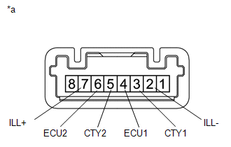
(b) Apply battery voltage to the connector and check the LED illumination.
OK:
|
Measurement Condition |
Specified Condition |
|---|---|
|
Battery positive (+) → Terminal 7 (ILL+) Battery negative (-) → Terminal 2 (ILL-) |
LED illuminates |
Installation
INSTALLATION
CAUTION / NOTICE / HINT
HINT:
A bolt without a torque specification is shown in the standard bolt chart (See
page .gif) ).
).
PROCEDURE
1. INSTALL SIDE AUTO STEP SWITCH ASSEMBLY
(a) Engage the 2 claws and install the side auto step switch assembly.
2. INSTALL LOWER INSTRUMENT PANEL FINISH PANEL SUB-ASSEMBLY
3. INSTALL NO. 1 INSTRUMENT CLUSTER FINISH PANEL GARNISH
4. INSTALL COWL SIDE TRIM BOARD LH
5. INSTALL DOOR SCUFF PLATE ASSEMBLY LH
 Removal
REMOVAL
PROCEDURE
1. DISCONNECT CABLE FROM NEGATIVE BATTERY TERMINAL
CAUTION:
Wait at least 90 seconds after disconnecting the cable from the negative (-)
battery terminal to disable the SRS sys ...

Other materials about Toyota 4Runner:
Dtc Check / Clear
DTC CHECK / CLEAR
1. CHECK DTC
(a) Connect the Techstream to the DLC3.
(b) Turn the engine switch on (IG).
(c) Turn the Techstream on.
(d) Enter the following menus: Body Electrical / Smart Key / Trouble Codes.
(e) Check for DTCs.
2. CLEAR DTC
(a) Conn ...
Meter Illumination is Always Dark
DESCRIPTION
This inspection is only for vehicles with automatic light control.
The meter CPU receives signals from this circuit to adjust the illumination of
the meter, instrument panel and accessory meter assembly. The meter CPU sets the
illumination le ...

0.027