Toyota 4Runner: AVC-LAN Circuit
DESCRIPTION
Each unit of the navigation system connected to the AVC-LAN (communication bus) transfers the switch signals using the AVC-LAN.
If a short to +B or short to ground occurs in the AVC-LAN, the navigation system will not function normally because communication is not possible.
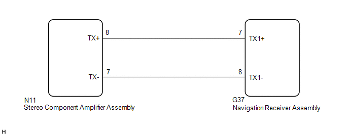
WIRING DIAGRAM
CAUTION / NOTICE / HINT
NOTICE:
After replacing the navigation receiver assembly of vehicles subscribed to pay-type satellite radio broadcasts, registration of the XM radio ID is necessary.
HINT:
The navigation receiver assembly is the master unit.
PROCEDURE
|
1. |
INSPECT NAVIGATION RECEIVER ASSEMBLY |
|
(a) Disconnect the G37 navigation receiver assembly connector. |
|
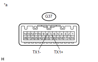
(b) Measure the resistance according to the value(s) in the table below.
Standard Resistance:
|
Tester Connection |
Condition |
Specified Condition |
|---|---|---|
|
G37-7 (TX1+) - G37-8 (TX1-) |
Always |
60 to 80 Ω |
|
*a |
Component without harness connected (Navigation Receiver Assembly) |
| NG | .gif) |
REPLACE NAVIGATION RECEIVER ASSEMBLY |
|
.gif)
|
2. |
CHECK HARNESS AND CONNECTOR (AVC-LAN CIRCUIT) |
(a) Disconnect the G37 navigation receiver assembly connector.
(b) Disconnect the N11 stereo component amplifier assembly connector.
(c) Measure the resistance according to the value(s) in the table below.
Standard Resistance:
|
Tester Connection |
Condition |
Specified Condition |
|---|---|---|
|
N11-8 (TX+) - G37-7 (TX1+) |
Always |
Below 1 Ω |
|
N11-7 (TX-) - G37-8 (TX1-) |
Always |
Below 1 Ω |
|
N11-8 (TX+) - Body ground |
Always |
10 kΩ or higher |
|
N11-7 (TX-) - Body ground |
Always |
10 kΩ or higher |
| NG | |
REPAIR OR REPLACE HARNESS OR CONNECTOR |
|
|
3. |
INSPECT MALFUNCTIONING PARTS |
(a) Disconnect and reconnect each slave unit one by one until the master unit returns to normal operation.
HINT:
- Check all slave units.
- If disconnecting a slave unit causes the master unit to return to normal operation, the slave unit is defective and should be replaced.
OK:
Master unit returns to normal operation.
| OK | |
REPLACE MALFUNCTIONING PARTS |
| NG | |
REPLACE NAVIGATION RECEIVER ASSEMBLY |
 Mute Signal Circuit between Stereo Component Amplifier and Telematics Transceiver
DESCRIPTION
The DCM (telematics transceiver) sends a mute signal to the stereo component
amplifier assembly.
The stereo component amplifier assembly controls the volume according to the
mute sig ...
 Vehicle Speed Signal Circuit between Stereo Component Amplifier and Combination
Meter
Vehicle Speed Signal Circuit between Stereo Component Amplifier and Combination
Meter
DESCRIPTION
The stereo component amplifier assembly receives a vehicle speed signal from
the combination meter assembly to control the ASL function.
HINT:
A voltage of 12 V or 5 V is outp ...
Other materials about Toyota 4Runner:
Park / Neutral Position Switch Circuit
DESCRIPTION
This circuit sends the park/neutral position switch assembly signals to the clearance
warning ECU assembly.
WIRING DIAGRAM
CAUTION / NOTICE / HINT
NOTICE:
Inspect the fuses for circuits related to this system before performing the followin ...
Lost Communication with Front Satellite Sensor Bus (B161A/8A)
DESCRIPTION
The front collision sensor circuit (front airbag sensor RH circuit and front
airbag sensor LH circuit) is composed of the center airbag sensor assembly, front
airbag sensor RH and front airbag sensor LH.
The front airbag sensor RH or front ai ...

0.0072