Toyota 4Runner: Back Door Courtesy Switch Circuit
DESCRIPTION
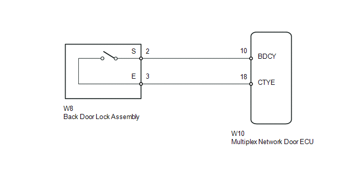
The multiplex network door ECU receives a back door open/closed signal from the back door lock.
WIRING DIAGRAM
PROCEDURE
|
1. |
READ VALUE USING TECHSTREAM (BACK DOOR COURTESY LIGHT SWITCH) |
(a) Using the Techstream, read the Data List (See page
.gif) ).
).
Back Door
|
Tester Display |
Measurement Item/Range |
Normal Condition |
Diagnostic Note |
|---|---|---|---|
|
Back Door Courtesy Switch |
Back door courtesy light switch signal / ON or OFF |
ON: Back door open OFF: Back door closed |
- |
OK:
Tester display changes according to opening and closing of back door.
| OK | .gif) |
PROCEED TO NEXT SUSPECTED AREA SHOWN IN PROBLEM SYMPTOMS TABLE |
|
.gif)
|
2. |
INSPECT BACK DOOR LOCK ASSEMBLY (BACK DOOR COURTESY LIGHT SWITCH) |
(a) Remove the back door lock (See page ).
.png)
(b) Measure the resistance according to the value(s) in the table below.
Standard Resistance:
|
Tester Connection |
Condition |
Specified Condition |
|---|---|---|
|
2 - 3 |
Open-latch |
Below 1 Ω |
|
Full-latch |
10 kΩ or higher |
.png) |
Full-latch |
.png) |
Open-latch |
| NG | |
REPLACE BACK DOOR LOCK ASSEMBLY |
|
|
3. |
CHECK HARNESS AND CONNECTOR (BACK DOOR LOCK ASSEMBLY - MULTIPLEX NETWORK DOOR ECU) |
(a) Disconnect the W8 back door lock connector.
(b) Disconnect the W10 multiplex network door ECU connector.
(c) Measure the resistance according to the value(s) in the table below.
Standard Resistance:
|
Tester Connection |
Condition |
Specified Condition |
|---|---|---|
|
W8-2 (S) - W10-10 (BDCY) |
Always |
Below 1 Ω |
|
W8-2 (S) - Body ground |
Always |
10 kΩ or higher |
|
W8-3 (E) - W10-18 (CTYE) |
Always |
Below 1 Ω |
|
W8-3 (E) - Body ground |
Always |
10 kΩ or higher |
| OK | |
REPLACE MULTIPLEX NETWORK DOOR ECU |
| NG | |
REPAIR OR REPLACE HARNESS OR CONNECTOR |
 IG Signal Circuit
DESCRIPTION
This circuit detects the ignition switch ON or off condition, and sends it to
the main body ECU.
WIRING DIAGRAM
CAUTION / NOTICE / HINT
NOTICE:
Inspect the fuses for circuits rela ...
 Door Courtesy Switch Circuit
DESCRIPTION
The main body ECU (multiplex network body ECU) receives a door open/closed signal
from each door courtesy light switch.
WIRING DIAGRAM
PROCEDURE
1.
READ VALU ...
Other materials about Toyota 4Runner:
Installation
INSTALLATION
PROCEDURE
1. INSTALL NO. 2 TELEPHONE BRACKET
(a) Install the bracket with the 2 bolts.
2. INSTALL NO. 1 TELEPHONE BRACKET
(a) Install the bracket with the 3 bolts.
(b) Connect the 2 connectors.
3. INSTALL MAYDAY BATTERY WITH BRACKET
(a) At ...
Cellular Phone Registration Failure
PROCEDURE
1.
CHECK USAGE CONDITION
(a) Check that the vehicle and cellular phone meet the following conditions:
NOTICE:
If changing cellular phone settings, updating software, etc. is necessary, make
sure to obtain the per ...

0.025