Toyota 4Runner: Back Power Window Switch
Components
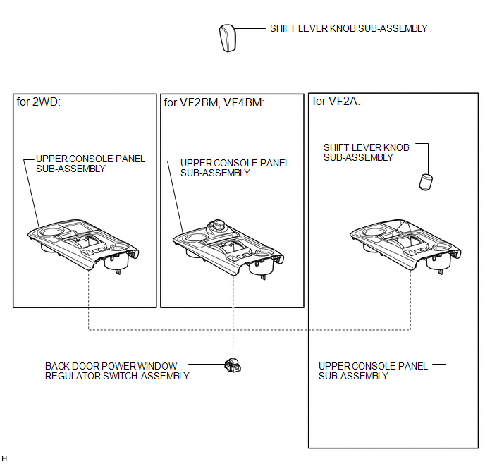
COMPONENTS
ILLUSTRATION
Removal
REMOVAL
PROCEDURE
1. REMOVE SHIFT LEVER KNOB SUB-ASSEMBLY
.gif)
2. REMOVE SHIFT LEVER KNOB SUB-ASSEMBLY (for VF2A)
3. REMOVE UPPER CONSOLE PANEL SUB-ASSEMBLY
4. REMOVE BACK DOOR POWER WINDOW REGULATOR SWITCH ASSEMBLY
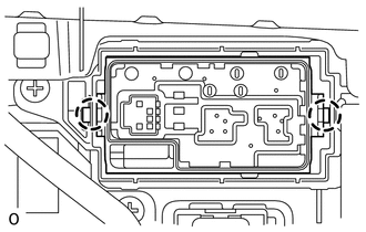
(a) Detach the 2 claws and remove the regulator switch.
Inspection
INSPECTION
PROCEDURE
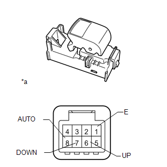
1. INSPECT BACK DOOR POWER WINDOW REGULATOR SWITCH ASSEMBLY
|
(a) Measure the resistance according to the value(s) in the table below. Standard Resistance:
|
|
Installation
INSTALLATION
PROCEDURE
1. INSTALL BACK DOOR POWER WINDOW REGULATOR SWITCH ASSEMBLY
(a) Attach the 2 claws to install the regulator switch.
2. INSTALL UPPER CONSOLE PANEL SUB-ASSEMBLY
.gif)
3. INSTALL SHIFT LEVER KNOB SUB-ASSEMBLY (for VF2A)
4. INSTALL SHIFT LEVER KNOB SUB-ASSEMBLY
 Installation
INSTALLATION
PROCEDURE
1. INSTALL BACK DOOR POWER WINDOW REGULATOR MOTOR ASSEMBLY
(a) Using a T25 "TORX" socket wrench, install the back power window regulator
motor assemb ...
 Front Passenger Side Power Window Switch
Components
COMPONENTS
ILLUSTRATION
Inspection
INSPECTION
PROCEDURE
1. INSPECT POWER WINDOW REGULATOR SWITCH ASSEMBLY
(a) Measure the resistance according to the value(s) in the ...
Other materials about Toyota 4Runner:
Precaution
PRECAUTION
1. PRECAUTIONS FOR EACH FUNCTION
(a) Precautions for the key:
The key is a precision instrument. Be sure to observe the following:
(1) Do not drop or strike the key.
(2) Do not keep the key in a high temperature area for a long ...
Removal
REMOVAL
PROCEDURE
1. PLACE FRONT WHEELS FACING STRAIGHT AHEAD
2. REMOVE FRONT WHEELS
3. REMOVE NO. 1 ENGINE UNDER COVER SUB-ASSEMBLY
Click here
4. REMOVE REAR ENGINE UNDER COVER ASSEMBLY
Click here
5. REMOVE FRONT DIFFERENTIAL CARRIER ASSEMBLY (for ...

0.027