Toyota 4Runner: Brake Actuator (Skid Control ECU) Communication Stop Mode
DESCRIPTION
|
Detection Item |
Symptom |
Trouble Area |
|---|---|---|
|
Brake Actuator (Skid Control ECU) Communication Stop Mode |
Either condition is met:
|
|
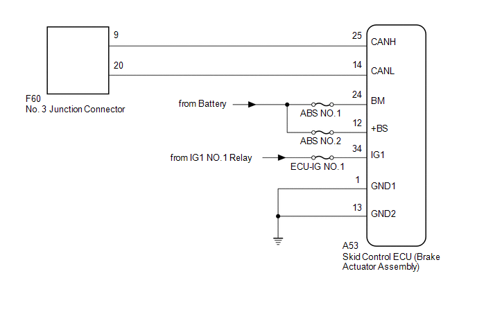
WIRING DIAGRAM
CAUTION / NOTICE / HINT
NOTICE:
Inspect the fuses for circuits related to this system before performing the following inspection procedure.
HINT:
Operating the ignition switch, any switches or any doors triggers related ECU and sensor communication with the CAN, which causes resistance variation.
PROCEDURE
|
1. |
DISCONNECT CABLE FROM NEGATIVE BATTERY TERMINAL |
(a) Disconnect the cable from the negative (-) battery terminal before measuring the resistances of the main wire and branch wire.
CAUTION:
Wait at least 90 seconds after disconnecting the cable from the negative (-) battery terminal to disable the SRS system.
NOTICE:
When disconnecting the cable, some systems need to be initialized after the cable
is reconnected (See page .gif) ).
).
|
.gif)
|
2. |
CHECK FOR OPEN IN CAN BUS WIRE (SKID CONTROL ECU BRANCH WIRE) |
|
(a) Disconnect the A53 skid control ECU (brake actuator assembly) connector. |
|
(b) Measure the resistance according to the value(s) in the table below.
Standard Resistance:
|
Tester Connection |
Switch Condition |
Specified Condition |
|---|---|---|
|
A53-25 (CANH) - A53-14 (CANL) |
Ignition switch off |
54 to 69 Ω |
|
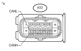
*a |
Front view of wire harness connector (to Skid Control ECU [Brake Actuator Assembly]) |
| NG | .gif) |
REPAIR OR REPLACE SKID CONTROL ECU BRANCH WIRE OR CONNECTOR (CANH, CANL) |
|
|
3. |
CHECK HARNESS AND CONNECTOR (SKID CONTROL ECU - BATTERY AND BODY GROUND) |
|
(a) Connect the cable to the negative (-) battery terminal. NOTICE: When disconnecting the cable, some systems need to be initialized after
the cable is reconnected (See page |
|
(b) Measure the resistance according to the value(s) in the table below.
Standard Resistance:
|
Tester Connection |
Condition |
Specified Condition |
|---|---|---|
|
A53-1 (GND1) - Body ground |
Always |
Below 1 Ω |
|
A53-13 (GND2) - Body ground |
Always |
Below 1 Ω |
(c) Measure the voltage according to the value(s) in the table below.
Standard Voltage:
|
Tester Connection |
Condition |
Specified Condition |
|---|---|---|
|
A53-12 (+BS) - Body ground |
Always |
11 to 14 V |
|
A53-24 (BM) - Body ground |
Always |
11 to 14 V |
|
A53-34 (IG1) - Body ground |
Ignition switch ON |
11 to 14 V |
|
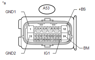
*a |
Front view of wire harness connector (to Skid Control ECU [Brake Actuator Assembly]) |
| OK | |
REPLACE SKID CONTROL ECU (BRAKE ACTUATOR ASSEMBLY) |
| NG | |
REPAIR OR REPLACE HARNESS OR CONNECTOR |
 Lost Communication with A/C ECU (U0164)
DESCRIPTION
DTC Code
DTC Detection Condition
Trouble Area
U0164
There is no communication from the air conditioning amplifier assembly.
...
 Skid Control ECU Communication Stop Mode
DESCRIPTION
Detection Item
Symptom
Trouble Area
Brake Actuator (Skid Control ECU) Communication Stop Mode
Either condition is met:
...
Other materials about Toyota 4Runner:
Installation
INSTALLATION
PROCEDURE
1. ADJUST COMPRESSOR OIL
(a) When replacing the compressor and magnetic clutch with a new one, gradually
discharge the refrigerant gas from the service valve and drain the following amount
of oil from the new compressor and magnet ...
Precaution
PRECAUTION
1. IGNITION SWITCH EXPRESSION
HINT:
The type of ignition switch used on this model differs according to the specifications
of the vehicle. The expressions listed in the table below are used in this section.
Expression
Ign ...

0.0284