Toyota 4Runner: Center Airbag Sensor Communication Stop Mode
DESCRIPTION
|
Detection Item |
Symptom |
Trouble Area |
|---|---|---|
|
Center Airbag Sensor Communication Stop Mode |
Either condition is met:
|
|
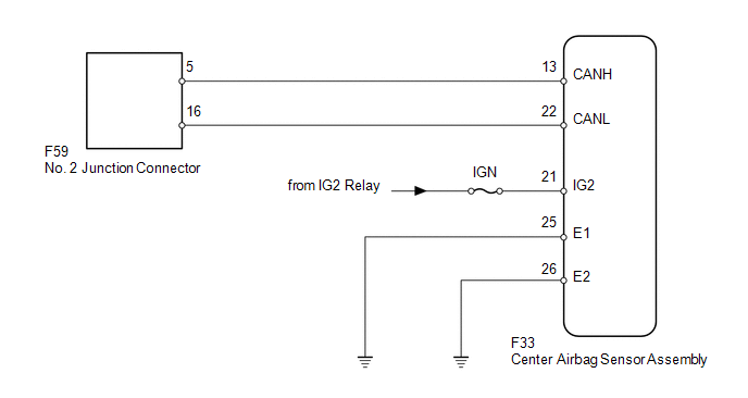
WIRING DIAGRAM
CAUTION / NOTICE / HINT
NOTICE:
Inspect the fuses for circuits related to this system before performing the following inspection procedure.
HINT:
Operating the ignition switch, any switches or any doors triggers related ECU and sensor communication with the CAN, which causes resistance variation.
PROCEDURE
|
1. |
DISCONNECT CABLE FROM NEGATIVE BATTERY TERMINAL |
(a) Disconnect the cable from the negative (-) battery terminal before measuring the resistances of the main wire and branch wire.
CAUTION:
Wait at least 90 seconds after disconnecting the cable from the negative (-) battery terminal to disable the SRS system.
NOTICE:
When disconnecting the cable, some systems need to be initialized after the cable
is reconnected (See page .gif) ).
).
|
.gif)
|
2. |
CHECK FOR OPEN IN CAN BUS WIRE (CENTER AIRBAG SENSOR ASSEMBLY BRANCH WIRE) |
|
(a) Disconnect the F33 center airbag sensor assembly connector. |
|
(b) Measure the resistance according to the value(s) in the table below.
Standard Resistance:
|
Tester Connection |
Switch Condition |
Specified Condition |
|---|---|---|
|
F33-13 (CANH) - F33-22 (CANL) |
Ignition switch off |
54 to 69 Ω |
|
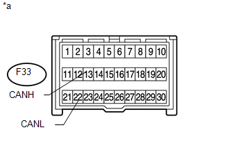
*a |
Front view of wire harness connector (to Center Airbag Sensor Assembly) |
| NG | .gif) |
REPAIR OR REPLACE CENTER AIRBAG SENSOR ASSEMBLY BRANCH WIRE OR CONNECTOR (CANH, CANL) |
|
|
3. |
CHECK HARNESS AND CONNECTOR (CENTER AIRBAG SENSOR ASSEMBLY - BATTERY AND BODY GROUND) |
|
(a) Connect the cable to the negative (-) battery terminal. NOTICE: When disconnecting the cable, some systems need to be initialized after
the cable is reconnected (See page |
|
(b) Measure the resistance according to the value(s) in the table below.
Standard Resistance:
|
Tester Connection |
Condition |
Specified Condition |
|---|---|---|
|
F33-25 (E1) - Body ground |
Always |
Below 1 Ω |
|
F33-26 (E2) - Body ground |
(c) Measure the voltage according to the value(s) in the table below.
Standard Voltage:
|
Tester Connection |
Switch Condition |
Specified Condition |
|---|---|---|
|
F33-21 (IG2) - Body ground |
Ignition switch ON |
11 to 14 V |
|
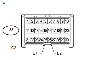
*a |
Front view of wire harness connector (to Center Airbag Sensor Assembly) |
| OK | |
REPLACE CENTER AIRBAG SENSOR ASSEMBLY |
| NG | |
REPAIR OR REPLACE HARNESS OR CONNECTOR |
 Certification ECU Communication Stop Mode
DESCRIPTION
Detection Item
Symptoms
Trouble Area
Certification ECU Communication Stop Mode
Either condition is met:
"Ce ...
 4WD Control ECU Communication Stop Mode
DESCRIPTION
Detection Item
Symptom
Trouble Area
4WD Control ECU Communication Stop Mode
Either condition is met:
"Four ...
Other materials about Toyota 4Runner:
Open or Short in Front Speed Sensor RH Circuit (C1405,C1406)
DESCRIPTION
Refer to DTCs C1401 and C1402 (See page ).
DTC Code
DTC Detection Condition
Trouble Area
C1405
C1406
Either condition is met:
An open in the speed sensor signal circui ...
Calibration
CALIBRATION
Initial Calibration of Compass:
The compass indicates the direction that the vehicle is heading by detecting
the direction and strength of the earth's magnetic field and processing this data
using the compass sensor and microcomputer. Det ...

0.0269