Toyota 4Runner: Certification ECU Power Source Circuit
DESCRIPTION
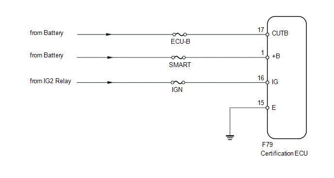
This circuit provides power to the certification ECU.
WIRING DIAGRAM
CAUTION / NOTICE / HINT
NOTICE:
Inspect the fuses for circuits related to this system before performing the following inspection procedure.
PROCEDURE
|
1. |
CHECK HARNESS AND CONNECTOR (CERTIFICATION ECU - BATTERY AND BODY GROUND) |
|
(a) Disconnect the F79 ECU connector. |
|
(b) Measure the voltage according to the value(s) in the table below.
Standard Voltage:
|
Tester Connection |
Switch Condition |
Specified Condition |
|---|---|---|
|
F79-1 (+B) - Body ground |
Always |
11 to 14 V |
|
F79-16 (IG) - Body ground |
Engine switch off |
Below 1 V |
|
F79-16 (IG) - Body ground |
Engine switch on (IG) |
11 to 14 V |
|
F79-17 (CUTB) - Body ground |
Always |
11 to 14 V |
(c) Measure the resistance according to the value(s) in the table below.
Standard Resistance:
|
Tester Connection |
Condition |
Specified Condition |
|---|---|---|
|
F79-15 (E) - Body ground |
Always |
Below 1 Ω |
|
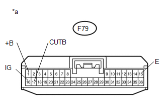
*a |
Front view of wire harness connector (to Certification ECU) |
| OK | .gif) |
PROCEED TO NEXT SUSPECTED AREA SHOWN IN PROBLEM SYMPTOMS TABLE |
| NG | |
REPAIR OR REPLACE HARNESS OR CONNECTOR |
 Engine Immobiliser System Malfunction (B2799)
DESCRIPTION
This DTC is stored when one of the following occurs: 1) the ECM detects errors
in its own communications with the ID code box; 2) the ECM detects errors in the
communication lines; or ...
 ID Code Box Power Source Circuit
DESCRIPTION
This circuit provides power to operate the ID code box.
WIRING DIAGRAM
CAUTION / NOTICE / HINT
NOTICE:
Inspect the fuses for circuits related to this system before performing the fo ...
Other materials about Toyota 4Runner:
Removal
REMOVAL
PROCEDURE
1. DISCONNECT CABLE FROM NEGATIVE BATTERY TERMINAL
NOTICE:
When disconnecting the cable, some systems need to be initialized after the cable
is reconnected (See page ).
2. REMOVE FRONT BUMPER COVER (w/o Intuitive Parking Assist System ...
Inspection
INSPECTION
PROCEDURE
1. INSPECT REAR NO. 1 SEAT OUTER BELT ASSEMBLY
(a) Check the ELR.
(1) When the inclination of the retractor is 15° or less, check that
the belt can be pulled from the retractor. When the inclination of the retractor
...

0.0226