Toyota 4Runner: Clearance Sonar Main Switch Circuit
DESCRIPTION
When the back sonar or clearance sonar switch assembly turns on, the on signal is input into the clearance warning ECU assembly.
WIRING DIAGRAM

CAUTION / NOTICE / HINT
NOTICE:
Inspect the fuses for circuits related to this system before performing the following inspection procedure.
PROCEDURE
|
1. |
INSPECT BACK SONAR OR CLEARANCE SONAR SWITCH ASSEMBLY |
(a) Remove the back sonar or clearance sonar switch assembly (See page
.gif) ).
).
(b) Inspect the back sonar or clearance sonar switch assembly (See page
).
| NG | .gif) |
REPLACE BACK SONAR OR CLEARANCE SONAR SWITCH ASSEMBLY |
|
.gif)
|
2. |
CHECK HARNESS AND CONNECTOR (BACK SONAR OR CLEARANCE SONAR SWITCH ASSEMBLY - BATTERY AND BODY GROUND) |
|
(a) Disconnect the F6 back sonar or clearance sonar switch assembly connector. |
|
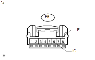
(b) Measure the voltage according to the value(s) in the table below.
Standard Voltage:
|
Tester Connection |
Switch Condition |
Specified Condition |
|---|---|---|
|
F6-6 (IG) - Body ground |
Ignition switch ON |
11 to 14 V |
|
Ignition switch off |
Below 1 V |
(c) Measure the resistance according to the value(s) in the table below.
Standard Resistance:
|
Tester Connection |
Condition |
Specified Condition |
|---|---|---|
|
F6-7 (E) - Body ground |
Always |
Below 1 Ω |
|
*a |
Front view of wire harness connector (to Back Sonar or Clearance Sonar Switch Assembly) |
| NG | |
REPAIR OR REPLACE HARNESS OR CONNECTOR |
|
|
3. |
CHECK HARNESS AND CONNECTOR (BACK SONAR OR CLEARANCE SONAR SWITCH ASSEMBLY - CLEARANCE WARNING ECU ASSEMBLY) |
(a) Disconnect the F6 back sonar or clearance sonar switch assembly connector.
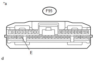
(b) Disconnect the F95 clearance warning ECU assembly connector.
(c) Measure the resistance according to the value(s) in the table below.
Standard Resistance:
|
Tester Connection |
Condition |
Specified Condition |
|---|---|---|
|
F6-3 (ECU) - F95-1 (IG) |
Always |
Below 1 Ω |
|
F6-3 (ECU) - Body ground |
Always |
10 kΩ or higher |
| NG | |
REPAIR OR REPLACE HARNESS OR CONNECTOR |
|
|
4. |
CHECK HARNESS AND CONNECTOR (CLEARANCE WARNING ECU ASSEMBLY - BODY GROUND) |
|
(a) Disconnect the F95 clearance warning ECU assembly connector. |
|
(b) Measure the resistance according to the value(s) in the table below.
Standard Resistance:
|
Tester Connection |
Condition |
Specified Condition |
|---|---|---|
|
F95-22 (E) - Body ground |
Always |
Below 1 Ω |
|
*a |
Front view of wire harness connector (to Clearance Warning ECU Assembly) |
| OK | |
PROCEED TO NEXT SUSPECTED AREA SHOWN IN PROBLEM SYMPTOMS TABLE |
| NG | |
REPAIR OR REPLACE HARNESS OR CONNECTOR |
 Rear Clearance Sonar Sensor RH Circuit
DESCRIPTION
The ultrasonic sensor sends and receives ultrasonic waves. Based on the received
wave, the sensor calculates the approximate distance between the vehicle and the
obstacle, and sends t ...
 Clearance Warning Buzzer Circuit
DESCRIPTION
The clearance warning buzzer sounds to alert the driver. The sounding pattern
changes depending on the distance to an obstacle.
WIRING DIAGRAM
PROCEDURE
1.
C ...
Other materials about Toyota 4Runner:
How To Proceed With Troubleshooting
CAUTION / NOTICE / HINT
HINT:
Inspect the window defogger system after confirming that the back door
power window system of the power window control system is operating normally.
Use these procedures to troubleshoot the window defogger sys ...
Disabling the TRAC/VSC systems (2WD models)
If the vehicle gets stuck in fresh snow or mud, the TRAC/VSC systems may
reduce power from the engine to the wheels. You may need to turn the system off
to enable you to rock the vehicle in order to free it.
Turning off the TRAC system only (turning on th ...

0.007