Toyota 4Runner: Combination Meter ECU Communication Stop Mode
DESCRIPTION
|
Detection Item |
Symptom |
Trouble Area |
|---|---|---|
|
Combination Meter ECU Communication Stop Mode |
Either condition is met:
|
|
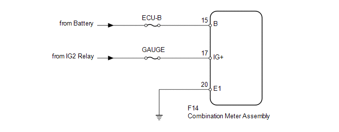
WIRING DIAGRAM
CAUTION / NOTICE / HINT
NOTICE:
Inspect the fuses for circuits related to this system before performing the following inspection procedure.
PROCEDURE
|
1. |
CHECK HARNESS AND CONNECTOR (COMBINATION METER ASSEMBLY - BATTERY AND BODY GROUND) |
|
(a) Disconnect the F14 combination meter assembly connector. |
|
(b) Measure the resistance according to the value(s) in the table below.
Standard Resistance:
|
Tester Connection |
Condition |
Specified Condition |
|---|---|---|
|
F14-20 (E1) - Body ground |
Always |
Below 1 Ω |
(c) Measure the voltage according to the value(s) in the table below.
Standard Voltage:
|
Tester Connection |
Switch Condition |
Specified Condition |
|---|---|---|
|
F14-15 (B) - Body ground |
Always |
11 to 14 V |
|
F14-17 (IG+) - Body ground |
Ignition switch ON |
11 to 14 V |
|
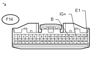
*a |
Front view of wire harness connector (to Combination Meter Assembly) |
| OK | .gif) |
REPLACE COMBINATION METER ASSEMBLY |
| NG | |
REPAIR OR REPLACE HARNESS OR CONNECTOR |
 Power Management Control ECU Communication Stop Mode
DESCRIPTION
Detection Item
Symptom
Trouble Area
Power Management Control ECU Communication Stop Mode
Either condition is met:
...
 Certification ECU Communication Stop Mode
DESCRIPTION
Detection Item
Symptoms
Trouble Area
Certification ECU Communication Stop Mode
Either condition is met:
"Ce ...
Other materials about Toyota 4Runner:
Trailer towing
Your vehicle is designed primarily as a passenger-and-load-carrying
vehicle. Towing a trailer can have an adverse impact on handling, performance,
braking, durability, and fuel consumption. For your safety and the safety of
others, you must not overload ...
Wheels
If a wheel is bent, cracked or heavily corroded, it should be replaced.
Otherwise, the tire may separate from the wheel or cause a loss of handling
control.
Wheel selection
When replacing wheels, care should be taken to ensure that they are
equivalent ...

0.0092